Gate Driver RF Amplifier
My last experiment was an attempt to create a driver amplifier that could get sufficient power into an IRF510 power transistor to make a few watts, and it was successful. But it was not ideal for my longer term goals – it was a class AB design that illustrated some issues with a push-pull driver arrangement, and is needlessly wasteful because I don’t need a linear amplifier for the transceiver I want to build.
Problem Statement
What I really need is an efficient non-linear amplifier. In my reading of EMRFD and a few other texts, I’ve been trying to understand class C operation. Along the way I found this fascinating article on class D, E, and F amplifiers. The author makes the point that a class C amplifier driven with a square wave instead of a sinusoid is a simple kind of class D amplifier.

Last time I used an IRF510, which has the benefit of being very cheap (less than $1 each) compared to purpose-made RF power transistors. Evidently, the big challenge with this device is its substantial gate capacitance (maybe 180pF!). Since the mosfet is voltage-activated, whatever drives the transistor must raise the voltage of the gate. But since it acts as a capacitor, it takes some time for current to fill that capacitance with charge, and thus raise the voltage.
E.g., at 12V, 180pF needs about 13nJ of energy to fill up. To drive a non-linear amplifier in class D with a hard square wave, we want to fill that capacitor in a short period… suppose 10ns for the 40m band. That takes 1.3W to drive the gate!
And apparently that’s a simplistic understanding, as this article from APM suggests that there are additional effects (including the Miller effect among others) that raise the apparent gate capacitance as the transistor passes into and through the linear region. The one they use seems to have a similar 180pF capacitance, and their figures suggest it reaches 2600pF before reaching saturation!
Since I plan to make a digital mode transceiver based on the Si5351 RF synthesizer chip, what I really want to do is flog the output transistor with scads of current to drive it as efficiently as possible into class D. This avoids the complexity of true class E and F operation, but gets me into the >70% efficiency zone. But how to drive the gate without a complex and lossy driver stage like last time?
A universal challenge with mosfets
In my research I discovered that driving high-capacitance MOSFET gates is not a problem unique to silly ham radio homebrewers trying to make a power hexfet do what it wasn’t really designed to. There are lots of other contexts where hard-driving a FET is important. And for this purpose, some wonderful engineer at International Rectifier invented the mosfet gate driver. These little guys are specifically design to take logic level input from chips that can’t take the heat and drive FET gates really hard (I guess usually for motor controllers and power supplies, etc.).
And there’s even a little prior art that I found in VK1SV’s article about a class-E amplifier. Here, Dimitrios describes a 2,200m band 50W amplifier where the TC4420 gate driver is used for much this same purpose.
Unfortunately, the TC4420 has rise and fall times that are way too long for more tractable amateur bands. The datasheet suggests 25ns. Assuming that we want the rise and fall times to be 5-10x less than the cycle time, this means I couldn’t really use the TC4420 above about the 80m band, and even there it might be kind of lossy.
A possible solution: MCP14A0601/2
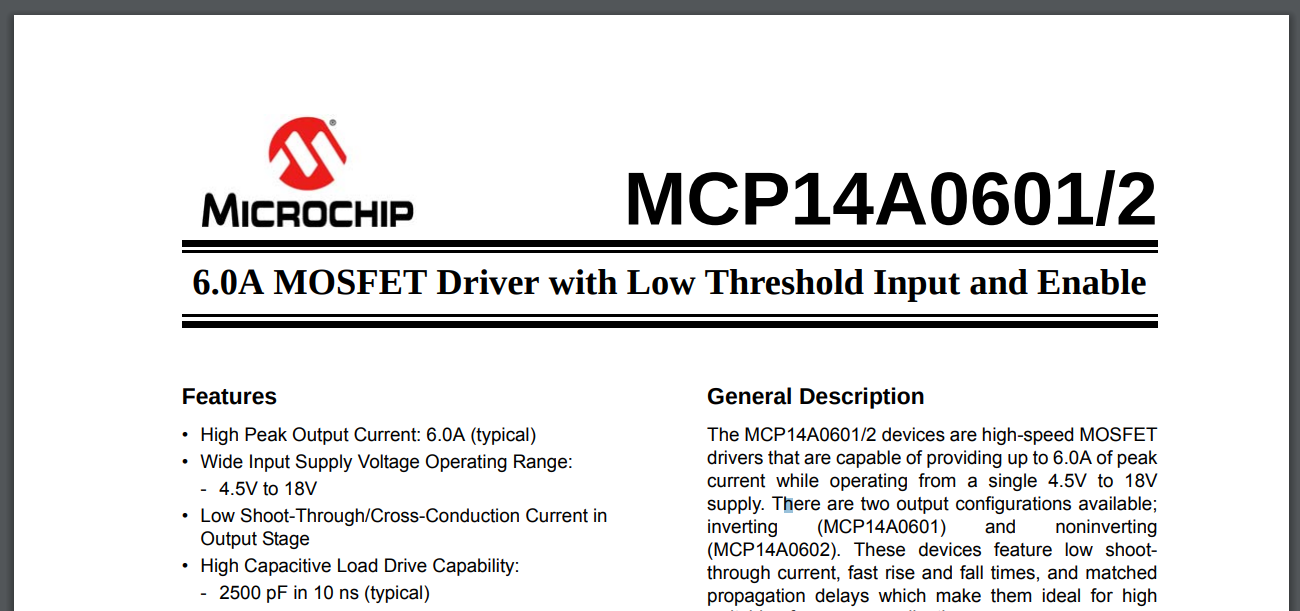
But that’s OK, this breadcrumb brought me to MicroChip, and they have a whole line of gate drivers. After reviewing a few datasheets, I discovered that the MCP14A0601/2 has rise times somewhat less than 10ns (depending on supply voltage and the driven gate capacitance). So, I wondered if this little beauty might be able to drive the IRF510 effectively.
To test this, I put together an idea of a circuit, using an Si5351 synthesizer, the MCP14A0601 gate driver, and an IRF510. This would be the first time I mill a PCB for surface mount parts, so I tentatively whipped up a little test board just to make sure that the footprints would work. It also gave me a chance to do a little testing with the driver to see how it might perform – One of the questions I had looking at the datasheet was how much bandwidth the gate driver can take (the datasheet charts only go up to 1MHz).
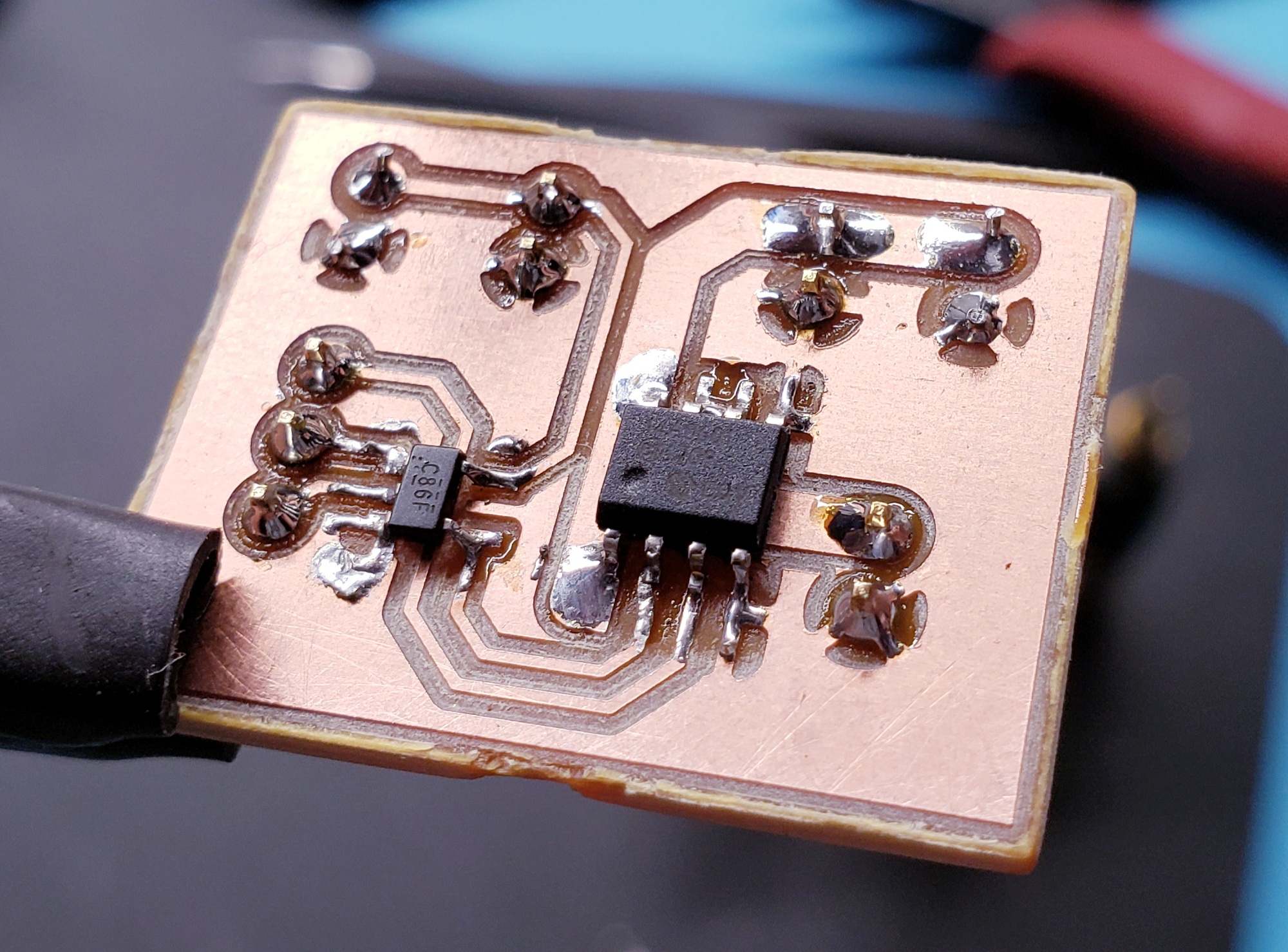
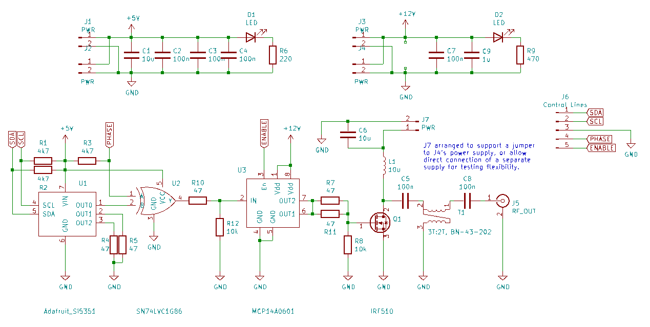
I was really happy with how this one came out, and it gives me increased confidence for using SMD parts in the future. The board worked, too, and suggested that the gate driver should function well at higher frequencies. With a couple observations in mind, I adjusted my tentative schematic, and came up with this:
Construction
Assembly of the board went well – I used an FT37-43 for the drain inductor on the IRF510 and a BN-43-202 for the output transistor. I designed the board for the Adafruit Si5351 breakout, but for initial testing, I just used my QRP Labs Progrock kit. This way I wouldn’t have to scrounge up a 5V-happy microcontroller and write code… I could just test my amplifier right away! (yes, ultimately I am just a big child, and get hasty with excitement)
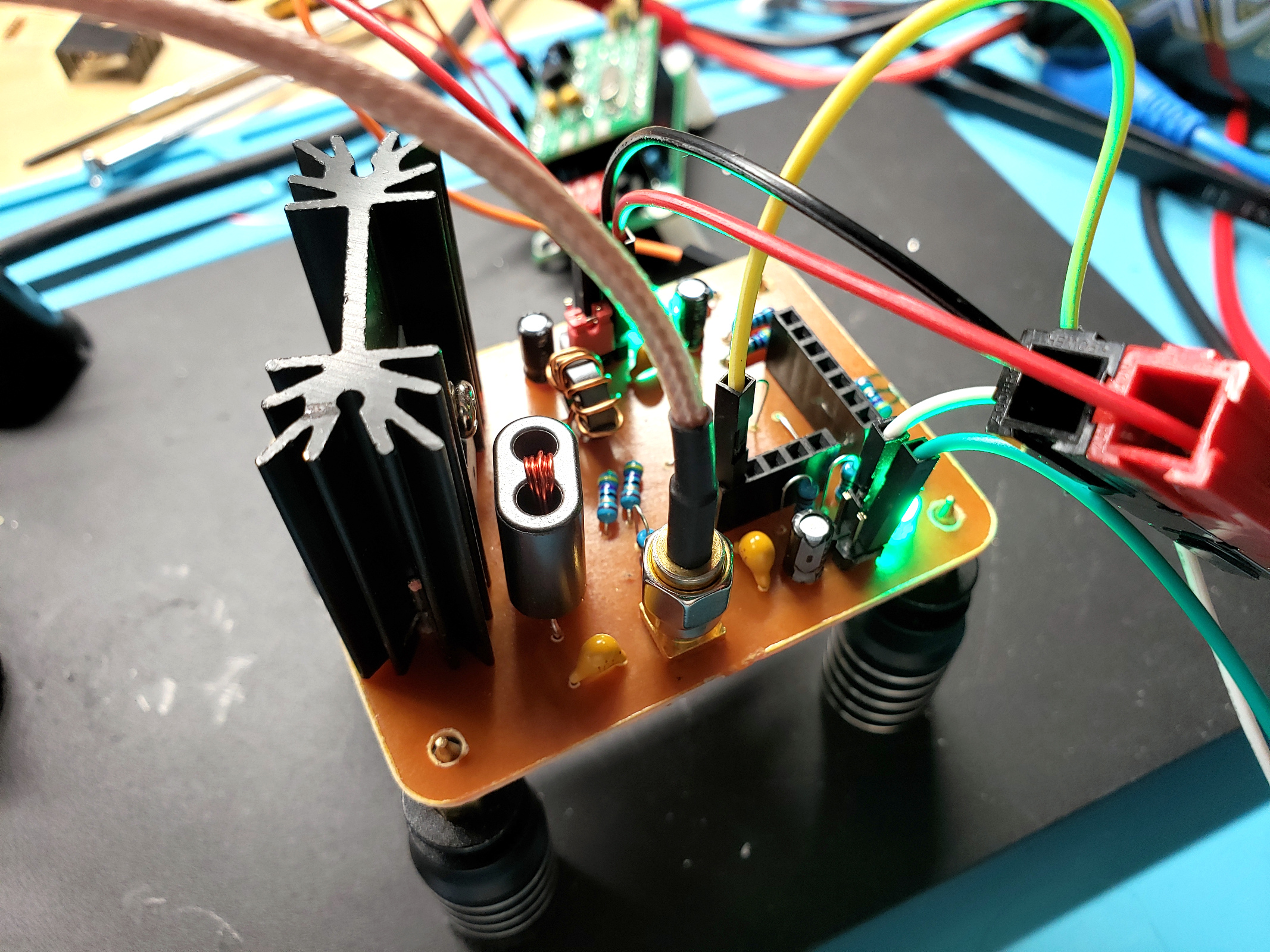
But, alas, disaster struck. No signal made it through the gate driver. I carefully probed things, and noticed that nothing made it through my XOR gate buffer. It’s there to do two things: (1) buffer the Si5351 output, and (2) give me a chance to do some tests with phase shifting (BPSK) if the board worked. But, it seemed the gate was perhaps dead.
Of course, in typical form it was not until this point that I realized that the XOR gate was simply the wrong choice. I had chosen it because the datasheet indicated it has a logic high voltage level of 1.7v. But when I looked more closely, I realized I’d misread that – it’s 1.7v if Vcc is 3-3.6v. When fed a solid 5.5v, the logic high level is 0.7*Vcc, which comes out to 3.85v. So the voltage level was just not enough to trip the gate.
Oh well, I already know that a XOR gate can give me BPSK. I can live with this test answering the most important question – whether the MCP14A0601 can drive the IRF510! So I removed it and bridged the signal from the Si5351 to the input to the MCP14A0601.
Test Results
And, the result was very exciting. With 6v of supply on the gate driver, I saw a nice 750mW of output into a 50 ohm load. This is testing at 7.1MHz through a 5th order Chebyshev low pass filter:
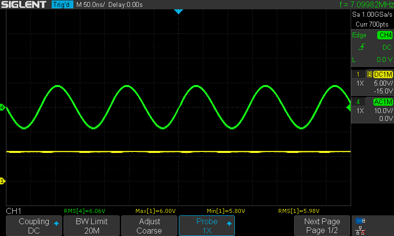
I gradually increased the supply voltage up to where I observed peak power output – 11v of supply yielded 5.2W output:
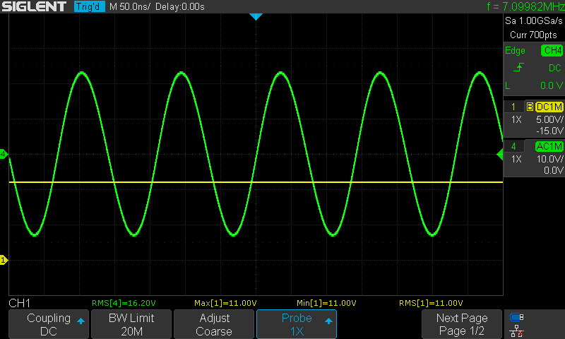
This is quite satisfactory. I believe some experimentation with the output transformer will probably increase the total output power. Also, due to a lack of power sources on my workbench, I don’t yet know what happens if I put 11v into the gate driver, but more supply voltage to the IRF510’s drain. I suspect power goes up then, too.
It’s worth pointing out here, as well, that at the maximum result (11v supply to the gate driver and IRF510), I’m seeing about 630mA of current draw. This means I’m getting 5.2W out for 7W in, making this amplifier about 75% efficient. There is some thermal behavior as well, if I let it run for awhile power goes up. In contrast to last week’s experiment, though, the heatsink never really gets significantly hot. Yay efficiency!
If I push the supply voltage on the gate driver much higher than 11v, I get some nasty distortion or oscillation. Here it begins to deteriorate at 11.8v:
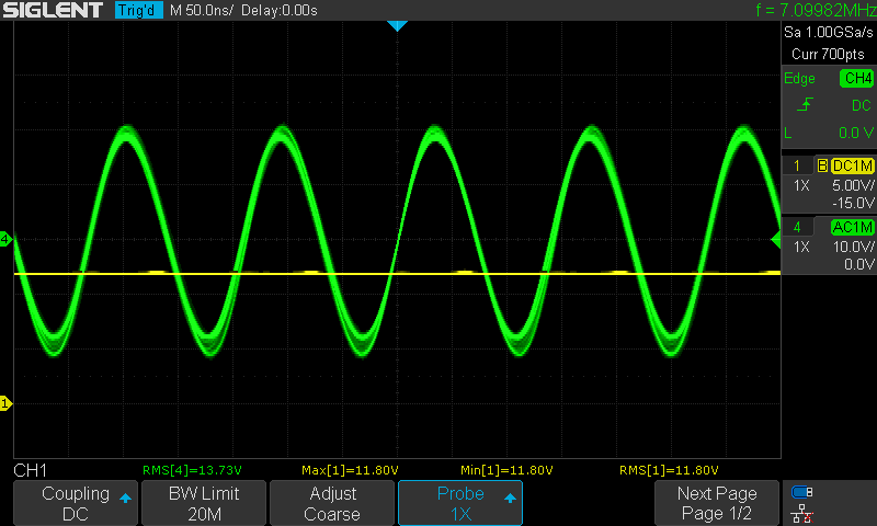
And it falls all apart at 12v:
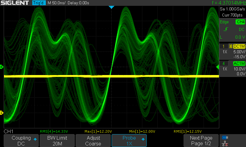
Investigating Signal Deterioration
The first thing I wanted to explore was controlling the oscillation while perhaps opening up the current to the IRF510’s gate a little more. I had placed two 47-ohm resistors between the gate driver and the mosfet gate, making for a 23.5 ohm resistance. I conducted tests removing these and replacing with different values, and found that about 20 ohms was necessary. At 10 or 15 ohms, there would be oscillation much sooner when increasing power or frequency.
I looked at the ARRL Handbook, and found that they suggest several strategies for mitigating oscillation. Resistors at the gate is one option, but some other possibilities include negative feedback and different placements of ferrites. Doing a little more reading, I found this excellent article from Microchip specifically about controlling fast-driven mosfets. This article favors the ferrite approach, and suggests:
If the ferrite beads are large and lossy enough, the gate resistors can be eliminated
Since the effect of the ferrite increases with frequency, I thought maybe this would allow more gate current at my desired fundamental frequency, while squashing the much higher frequency oscillations. I picked up a bag of Fair Rite 5943000901s from Digikey not too long ago, which are some tiny 6mm mix 43 toroids. Online calculators estimated they should be less than my 23 ohm resistors at 7.1MHz (about 12 ohms or so) with one turn:
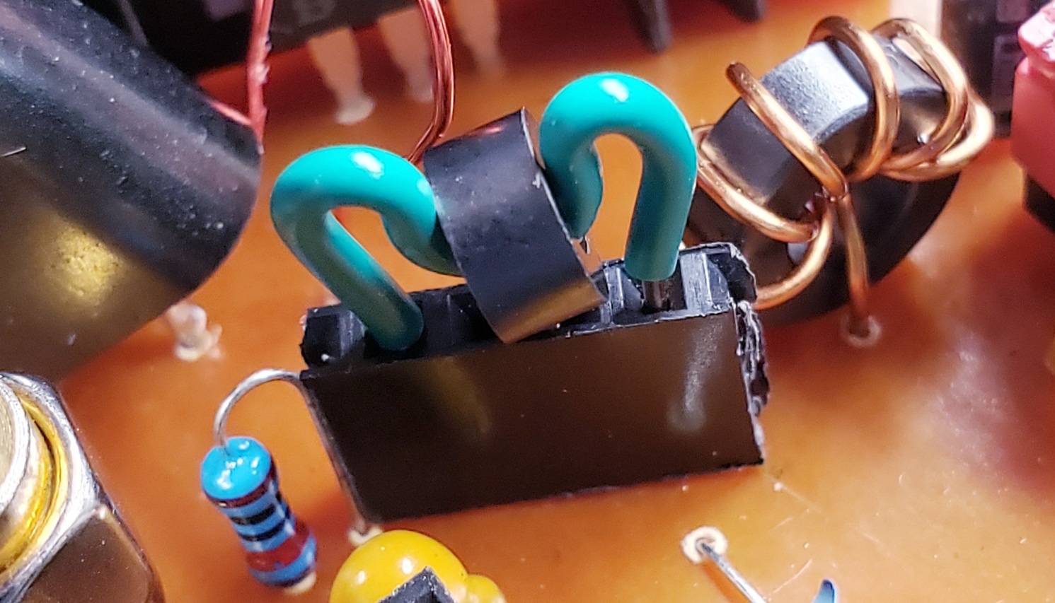
And indeed, the next few tests showed slightly better performance and with less oscillation. I could push frequency and power up just a bit without oscillation. So I concluded that this single pass through the ferrite approach worked great. I think I’ll want to get some even smaller ferrite rings. An FT23-43 is somewhat smaller than these, and might work just as well?
During this testing, I noticed another behavior. There seemed to be some frequency and supply dependent effect on the duty cycle. For example, here is a contrast at 7.1MHz between 7v supply (left) and 11v (right):

This was quite interesting, so I did a series of tests at frequencies from 4MHz to 10MHz and supply voltages from 7v to 11v. The results can be seen in the following graph:
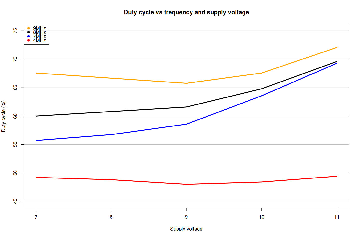
The duty cycle increases with frequency and (generally) with supply voltage. It’s not perfectly consistent, but it made me start to wonder what’s going on. After a quick review of the MCP14A0601 datasheet, I saw that on page 7 there are several graphs showing variability in input propagation delays and such, and there is discussion of rise and fall time calculation. But what I’m observing here doesn’t necessarily match what is shown there.
It seems like this gate driver works fine up to the 40m band, but much higher and these frequency and supply dependent effects become problematic. I looked at some more gate drivers, and for a little increase in price ($1.39 on Mouser), the Texas Instruments UCC275x series looks like it might perform better at higher frequencies. It might be worth grabbing one and playing with it to see if it exhibits similar behavior.
Conclusions and Next Steps
I am really excited that a little bit of research and reading up on things lead to another working amplifier, this time with a wildly different design. Getting 5W out for 7W in is a milestone for my homebrew amplifier projects. When I first started playing with RF amplifiers, just getting to 50% seemed like an unattainable dream!
In this case, I used the MCP14A0601, which is the inverting version of the gate driver. There is also an MCP14A0602, which is the non-inverting one. The datasheet says these devices feature “… matched propagation delays which make them ideal for high switching frequency applications.”
This makes me suspect that both devices together could drive a pair of IRF510s in a push-pull configuration, perhaps yielding better performance (something similar can be seen in that APM article I linked above, so it’s not too crazy a thought!). This will be my next experiment. If it goes well, it may be the amplifier design I choose for my upcoming digital transceiver project!
And finally, this experiment raises interesting questions about oscillation and the limits of this circuit. I’m not sure exactly how to describe what happens at higher supply voltages. Is it because it’s driving the IRF510 gate to 12v? (IRF510’s data sheet says 20v is within spec, but maybe at RF all bets are off?) The behavior seems quite stable under the 11.8v threshold; I’ll have to read up on these things and see what I can learn.