IQ Sampling and Phasing Receivers
IQ sampling is a technique used all over the place, from hobby software defined radio (SDR) systems to cell phones. Even though I’ve been an SDR enthusiast for a number of years, the underlying principles that make IQ sampling work have been a mystery to me. Recently, I’ve turned my attention to RF receiver design, and some thought experiments have really opened it up to me.
This blog post presents what I think is the best intuitive, math-lite explanation of IQ mixing, why it’s significant, and how it works in phasing receivers (and lots of real-world devices).
We can’t hear plaid
Before jumping into things, let’s set up the main problem with RF receiving – we as humans don’t perceive the electromagnetic spectrum until frequencies get really high… like terahertz[1]. RF technologies depend on signals at frequencies from (practically speaking) hundreds of kilohertz to perhaps dozens of gigahertz. Too high to hear if we were to turn them into sound waves, and too low to see with our eyes!
So the first order of business is somehow scaling the signals coming into our antenna to something we can perceive. Except for some exotic (and very exciting) direct sampling approaches that depend on what is currently pretty expensive hardware, almost all RF devices use mixing to move a signal from one frequency to another.
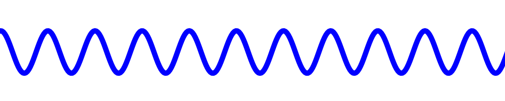
An RF mixer essentially multiplies two oscillating signals together. Mixers vary in exactly how they do this[2], but for now we’ll hand-wave over some of the details and assume we have a perfect kind of mixer. Let’s start with a signal coming into our antenna at some frequency:
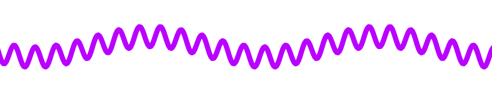
If we multiply this signal with another signal, a little bit lower in frequency, we get an interesting result. The output has two components – there is a high frequency overlayed on a low frequency. These are the sum and the difference between the two signals we mixed, and it’s basically a property of multiplying sine waves:
We’re not so interested in that high frequency, so we can apply a “low pass filter”, which allows low frequencies through, but blocks high ones. Doing so with the above signal, we see just the low frequency pop out:
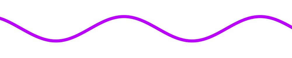
This is how a mixer can take a signal at a very high frequency (think: many megahertz) and “translate” it to a very low frequency that can drive a speaker and we can hear. We call the wave we mix with the signal coming in on the antenna our “local oscillator” or LO. We can change the frequency of our LO and tune around the RF spectrum, mixing signals down to audible frequencies, and listen to signals with our ears!
A closer look at basic mixing
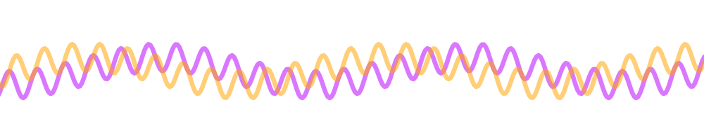
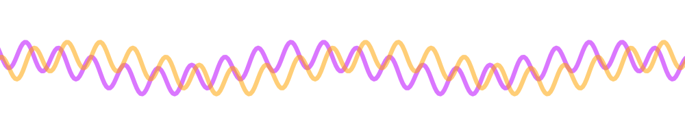
To make what’s happening when we multiply a little more intuitive, look at this visualization of two waves graphed on top of one another:
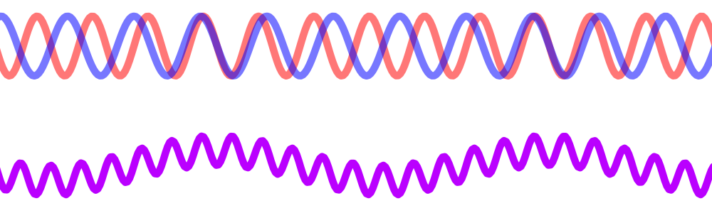
There is “aliasing”, where the two waves seem to overlap sometimes, but other times they are exactly the opposite[3]. The low frequency high points in the mixing result correspond with those places where the waves most closely overlap, whereas the low points correspond to those places where they are opposites. We’ll come back to aliasing later, because it’s an important part of IQ mixing!
In real life, when you mix signals from your antenna with your LO, you can’t tell if the signals you hear were above or below your tuned frequency[4]. Multiplication works in both directions, after all. What we need is some way to discriminate between waves above and below – called the upper and lower “sidebands”. This is where IQ mixing comes in, and it can seem a little magical.
The 7MHz roller coaster
Einstein used a famous thought experiment while formulating special relativity – he imagined he was following along with a light beam at the speed of light. Let’s do the same sort of thing, but with these signals that we’re mixing.
Imagine you are riding a sinusoidal roller coaster at, say, 7MHz. You rise with each peak and looking ahead you see an unending series of future peaks leading off into the distance. Then, falling into the valleys between (while screaming WHEEE!), you anxiously await the next time you reach the top.
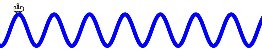
At some point, you notice another roller coaster along side of you. But its peaks come a little sooner every time than your own. You crest a peak, and you see that this other signal has a peak that will come just short of your next one. Down through the valley, your car comes up again, and you see that the other signal’s peak is even closer.
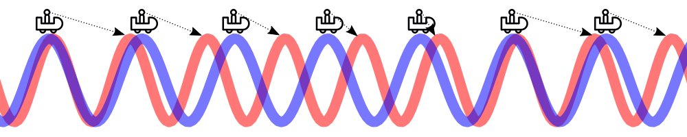
Over time, it feels as if this other wave is moving towards you. Eventually, your peaks are right next to each other, and then it’s gone… but there’s another on its way ahead! Like one of Dr. Who’s weeping angels, every time you look, you see the other wave getting eerily closer. Don’t blink! This is the behavior of a higher frequency wave.
Now, consider another signal that comes alongside – only it’s a lower frequency. What happens is that you reach a peak, and notice that there is another peaking roller coaster right next to you. You go down into a valley, and come up on the next peak. And there, you see that the peak has moved along, slightly farther away than last time. It takes longer for this other signal to reach its peaks than yours.
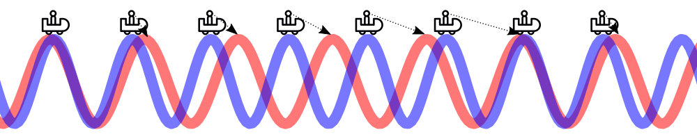
This wave appears to move away from you over time, which makes sense since it’s a lower frequency and plods through space with fewer peaks per unit distance.
With this thought experiment in mind, we can see that there is a fundamental difference between signals that are higher frequency than our local oscillator versus those that are slower: higher frequencies alias “toward” us, and lower frequencies alias “away”. If we can find some way to extract this directionality from the mixer, we can tell the upper sideband from the lower sideband!
I & Q: two local oscillators
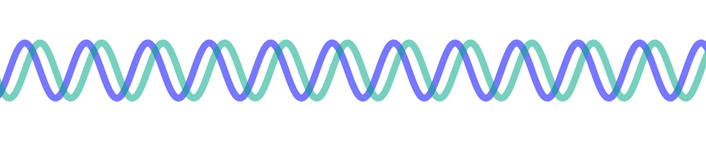
The stroke of genius in IQ sampling is that we can do exactly that, and in a (theoretically[5]) perfect way with respect to all signals coming into our mixer. What we do is mix the incoming signals with two local oscillators, but with a slight twist – they’re the same frequency, but these two oscillators are 90-degrees apart. They are in “quadrature”:
Returning to our roller coaster thought experiment, what will happen as a higher frequency signal comes along in our mixer? It will alias towards us as we ride the wave. But since we have two local oscillators, the incoming peaks will align with the second of our two LO signals first. After a quarter cycle, then it will align with the first LO signal. This means that a higher frequency will peak the second LO ahead of the first LO. It’ll look like this:
Now, what happens with a lower frequency? Its peaks alias away from us, so it will align with the first LO signal first, followed 90 degrees later by the second. This means that in the mixing product peaks, the first LO will precede the second – the exact opposite of what happened with the higher frequency.
So, with any signal that is in the lower sideband (LSB) the first LO will precede the second LO in the mixing products. Any upper sideband (USB) signal will be the other way around, with the second LO preceding the first LO. We call the first LO “I”, for “in phase”, and the second “Q”, for “quadrature”.
Why 90 degrees?
You might wonder then, if the detection of the sideband is due to a phase difference in the local oscillators, couldn’t it be any difference? Why 90 degrees? There’s a little bit more magic yet to come!
In principle you could observe the same phasing behavior with another phase shift. But 90 degrees is special. You can apply another phase shift and add the two results together to eliminate one of the sidebands entirely. And this is, in fact, how a lot of real radios get a clean representation of one sideband.
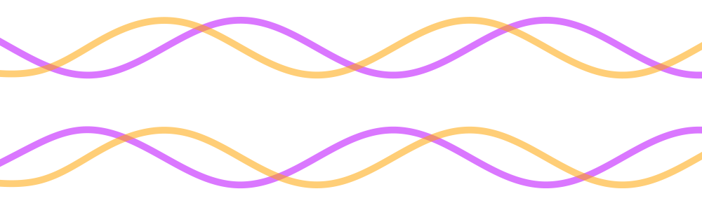
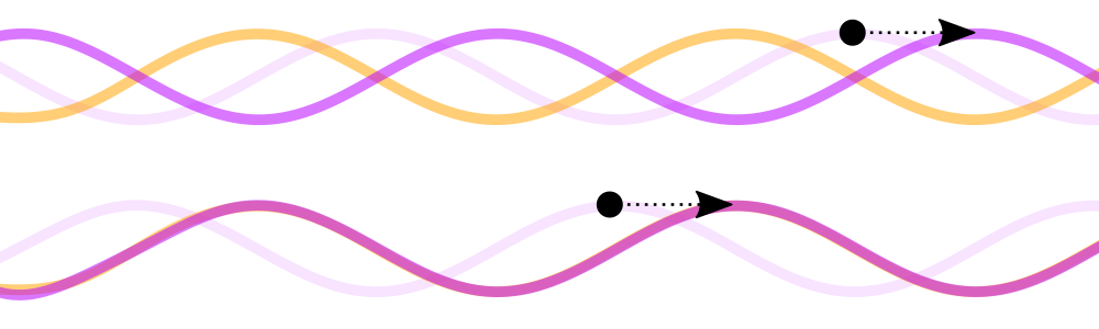
Take the following pair of mixing products, one with a lower frequency and one with a higher one, with respect to the local oscillator. Note I’ve low-pass filtered them for clarity:
Imagine that we shift the purple line left 90-degrees[6]. What do we see? It is exactly aligned with one of the two frequencies, and exactly the opposite of the other:
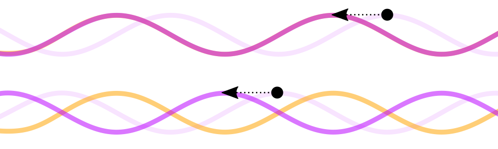
Adding these together, we can see that only signals in one of the sidebands can come through! This is the magic of image rejection in a phasing receiver. If we wanted the other sideband, we can just shift the purple signal the other direction:
IQ mixing and SDRs
We can use IQ mixing, a phase shift, and a combiner to make a completely analog receiver that just has good sideband rejection (that way we don’t hear signals from the other sideband overlapping the ones we’re trying to hear!).
But going further, we can use I and Q as inputs to a complex Fourier transform (FFT). While beyond the scope I want to get to in this blog post, this allows a software processor to identify signals in both sidebands with all phase shift information necessary to demodulate (in principle) any kind of modulated information.
Also, IQ sampling works in reverse – you can calculate the I and Q signals that you want, run the process in reverse, and mix “up” to the RF frequency you want to transmit. A complete SDR transceiver can operate this way and achieve any modulation desired.
Conclusions
I’ve been laboring to understand the guts of IQ sampling for a long time. Most descriptions you find are based on pure math derivation. Articles that try to explain it will often show some trig equations, receiver block diagrams, and spectrum analyzer outputs. Those explanations left me accepting the truth of IQ mixing, but left too much magic in there for me to really understand.
As I formulated my little thought experiment, and graphed some sine waves with each other, I found that this brought a bunch of things clicking into place. I can’t say I know everything about IQ sampling, or that this description is the whole story. But it certainly helped, and I hope it is helpful for anyone who comes upon this blog post.
Learning physics is fun!
[1] Red light, which is the lowest frequency light we can see is around 430 terahertz. It has to be high enough frequency that the wavelengths are short enough that our eyeballs can be equipped with cells that receive these signals. Cone cells in our eyes are about 400-500nM, which means they’re on the right scale for sensing light, with red light coming in around 600nM in wavelength.
[2] Some mixers do seem to produce a proper multiplication, but others work in counterintuitive ways. Switching mixers essentially multiply a signal by a square wave, which is like multiplying by -1 and +1 at the rate of the LO – this is still multiplication, but it adds lots of harmonics and can make the output waveform look kind of odd (harmonically, pun intended, hah!). Nevertheless, there is multiplication buried in there, but for the purposes of this blog post I find proper continuous multiplication to make the principles easier to see!
[3] Signals that are harmonically related (one being an even multiple of the other) will not “alias” like this, because alternate peaks on the higher frequency will always align with peaks in the lower frequency. They’ll still mix, but there are some interesting consequences (e.g., they start to look like square waves coming out of the mix!).
[4] Actually, you can – you can listen to the signal while you adjust the LO. If the signal is above the LO, the tone will go down as you raise the frequency, whereas a signal below will get higher in pitch. But that’s not ultimately helpful if we’re trying to avoid receiving signals on the unwanted side of our LO frequency.
[5] I say theoretically because there are complicating issues like jitter, phase noise, thermal noise, etc., that do put some limits on how well we can pull it off. But relative to our needs, we might as well call even reasonably modest setups “perfect enough” to get a good handle on the spectrum around our local oscillator frequency.
[6] OK, achieving a precise phase shift over a wide bandwidth is a real challenge, whether you’re using analog circuitry or software to shift the phase. Fortunately, for RF reception, we often only need to phase-shift across a tiny bandwidth. It would be hard to achieve a very wide-band phase shift. For human hearing, though, we max out at 20KHz or so, and for speech over the radio only 2-3KHz is really necessary. Much more than that, and we’re probably talking about SDR and FFT processing, which is a different animal entirely!