Coax to stereo audio connector
OK, this is a little thing, but I couldn’t believe I can’t find this kind of connector inexpensively on Amazon. So tonight, I whipped up this little PCB and soldered on some connectors. So, now with my RF receiver experiments, where I’m putting out I and Q signals into stereo headphone jacks, I can easily see them on the oscilloscope!
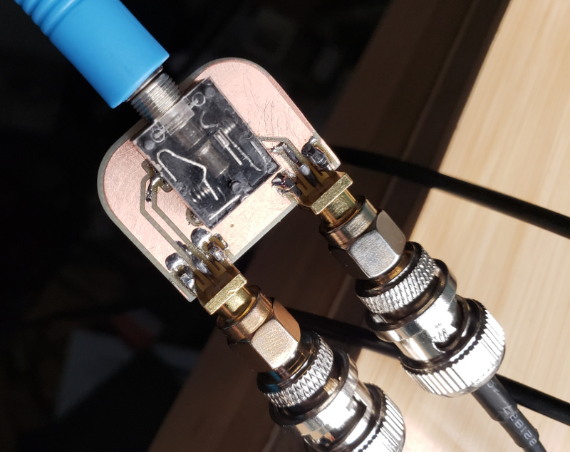
I made a couple goofs making it, the worst of which was forgetting to flip the footprint, so the pins are backwards. But I was able to stand it up about a 1mm off the board, and flow solder into the pins with very minor melting of the 3.5mm jack’s case. Oops! At least now the second one I make (and I’ll need two eventually, I just ran out of the board-edge SMA connectors and could only make one tonight) will be right.
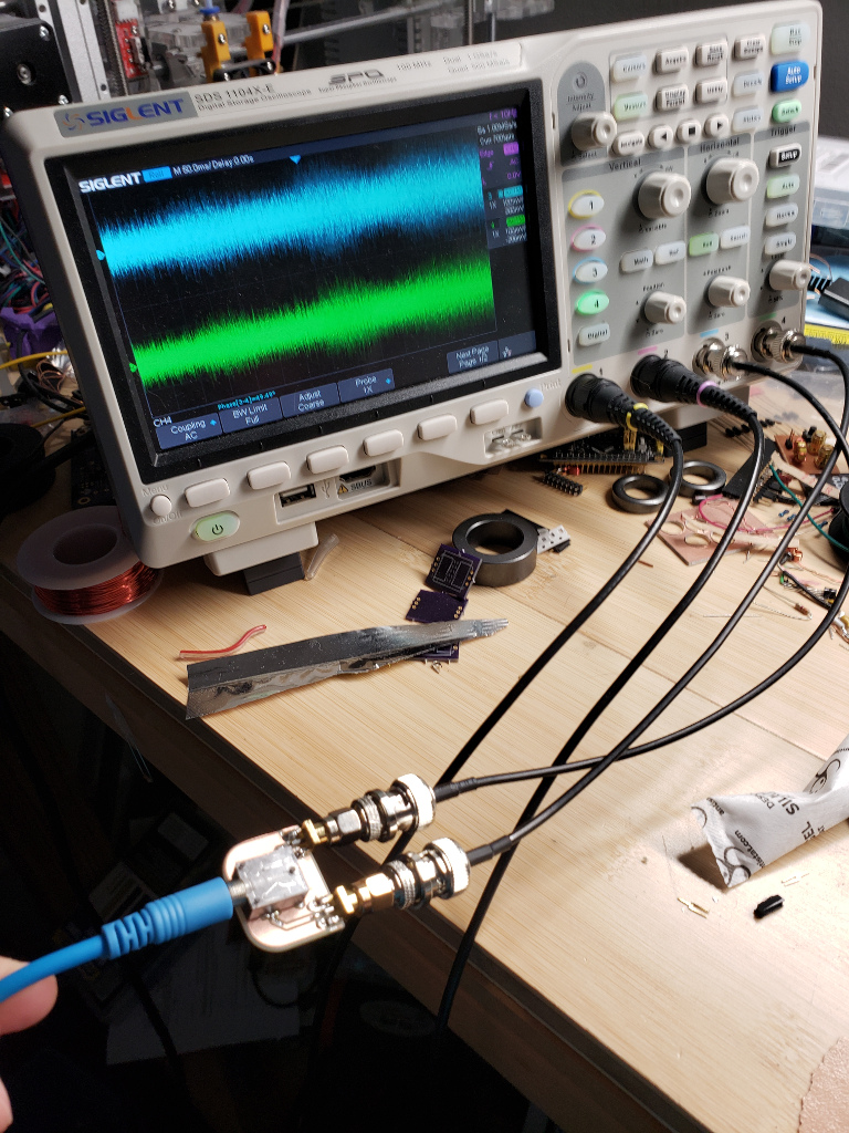
This image shows a little test, with my latest Tayloe detector receiver board’s IQ output to the oscilloscope. This is using the “roll” mode on the scope, so it’s running at “realtime”. It’s fun to watch, but it looks like a mess in the still image. The signals are making it in just fine, though, and the connector is working great.
This should give me some improved fidelity to characterize my receivers with, in contrast to the gaggle of wires, screw terminals, and coax adapters I’ve had to use thus far.
I can’t be the only person who wants a stereo 3.5mm -> double coax connector, can I?