Another Receiver Board
I’ve now built a couple of Tayloe detector-based receivers, and thought I should try my hand at one that’s a little more traditional. This post describes an analog double sideband direct conversion receiver, and documents my results. It’s not ultimately a very good receiver, but going through this process taught me some things, and I’ve come away from it with thoughts on where I’ll go next.
I’ve read a good bit of EMRFD at this point, and the authors of that book, and some others I’ve read elsewhere, talk about the importance of building a simple, direct conversion receiver as a developmental stage in homebrew transceivers. Even though the Tayloe detectors I’ve built are direct conversion, I’ve actually been overshooting in complexity, with image rejection, phasing for single sideband operation, etc. It seemed like I should honor the wisdom of these authors, and pursue a simple DSB receiver, built around a diode ring mixer, etc.
The Mixer
The first thing I did was build a diode ring mixer. It came out quite well, looking like the image below. I wanted to start this way because I don’t like just grabbing a ready-made component I can plausibly build myself – by going through the exercise, I feel like I really internalize what’s going on. Of course, a commercial diode ring mixer uses snazzier diodes, ideal transformers, and commits to excellent specifications, so there’s no reason not to use them once I know how to make one myself! I hooked this guy up to the oscilloscope and used my signal generator to run a bunch of experiments, to figure out what it looked like for important attributes, like isolation, conversion loss etc.
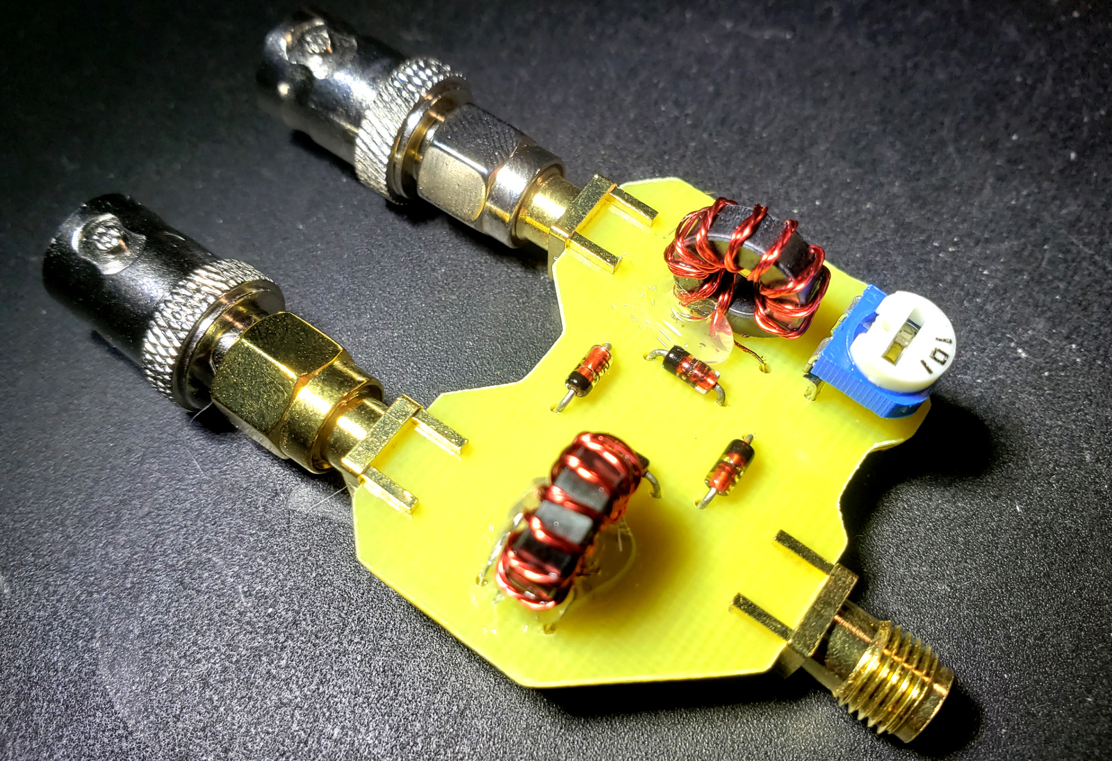
Turns out, I did OK, based on what I read. I used Charlie Morris’s approach of adding a potentiometer at one port to tweak balance, though the sweet spot turned out to be so close to the middle of the POT, I suppose it wasn’t necessary. I found I was getting something like -7.4dB conversion loss, and my LO isolation was in the neighborhood of -30-40dB. OK, I guess for some junk box diodes (though I did do some matching with my multimeter’s diode test function), and hastily wrapped toroids.
Anyway, after a successful foray into diode ring mixers, I selected the Minicircuits ADE-1+ to build my receiver around. It has much nicer specs – 5dB of conversion loss or so, and 60-70dB of isolation in the lower HF bands. Pretty fancy stuff – but a little pricey! Too bad Minicircuits was out of stock at the time, I had to buy from Mouser, who charges a premium for small quantities!
The Schematic
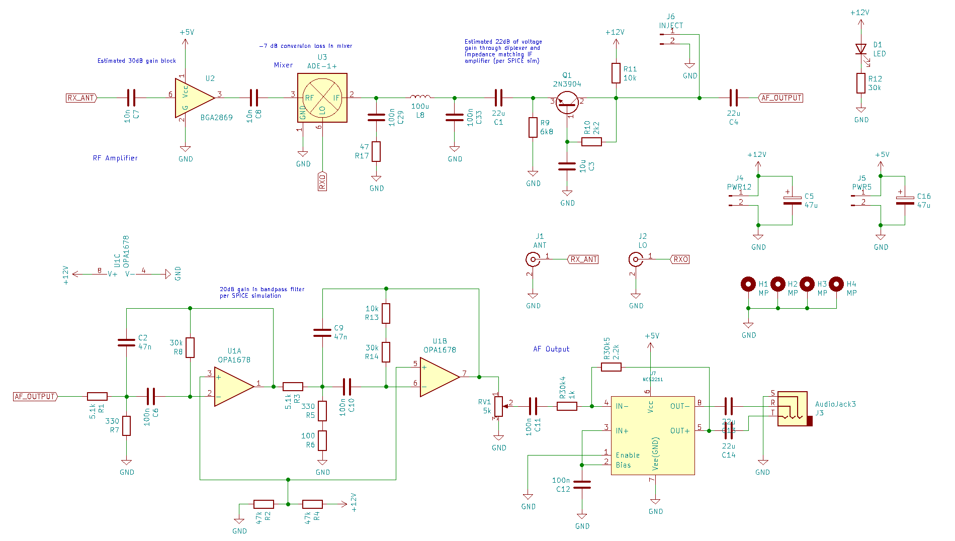
Let’s talk through the schematic a bit – as I said before, this isn’t a very good receiver, but it was at least a starting point for me to play around with some more complicated stuff than I have so far.
Someone I had talked to recently told me about these little BGA2869 MMIC gain blocks from NXP. They are described as DC-2GHz amplifiers, internally matched to 50-ohm inputs and outputs, and require no special components for biasing, etc. So much magic in a little package, I had to throw one in somewhere. Without knowing whether it’s a good idea or not, I just slapped one on the front end of the mixer, figuring I’d get a probable 30dB of RF gain off the bat. Turns out, it was a little complicated, but I’ll get to that later :-).
After the mixer, there is an interesting set of options. I read through the articles from KK7B and his well-reputed direct conversion receivers. One thing he talks about, and I found some discussion in EMRFD about it too, is the need to properly terminate the output of the mixer for all signals coming through it. I guess the point is that you don’t want to have a bad termination, and get signals reflecting off your baseband stages back into the mixer, wreaking havoc.
The designs I reviewed use a diplexer after the mixer to shunt the RF mixing products to a terminating resistor, while passing the low frequency audio signals into an amplification stage that needs to have a good 50-ohm match. Evidently, this is not one of those cases where “close” is good enough – some authors suggested even a small mismatch can have a measurable impact on performance.
So I took the common base BJT amplifier I saw frequently in various designs (I suppose it’s been handed down through generations…), and tweaked it. I wanted to make it a little simpler, and so I spent some time in LTSpice tweaking things until it seemed like it should have a good 50-ohm match, and tossed it in. I think this is one of the things on this board that “just worked” and didn’t really require any modification after the fact.
After a round of amplification, I toss the signal into two opamp stages to apply some audio frequency bandpass filtering. I designed this filter in the Iowa Hills software, and in the process learned some things. I’ll get to some of the conclusions in a bit.
Finally, I’ve read so many laments about how everybody just throws an LM386 in for an audio amp, and how it’s such a bad chip, and it hisses, and it’s inefficient, and it’s old fashioned, etc. So I thought I’d try something different. I did some online forum research, and found that there are a few chips that people like to use that are more modern, though to be honest, I can’t find an actual drop-in modern replacement for the LM386. It seems that the ideas in that classic chip’s design are simply no longer en vogue. I settled on the NCS2211, and basically copied the reference schematic from the datasheet. Well, I thought I copied it… but that would be getting ahead of myself! (spoilers!)
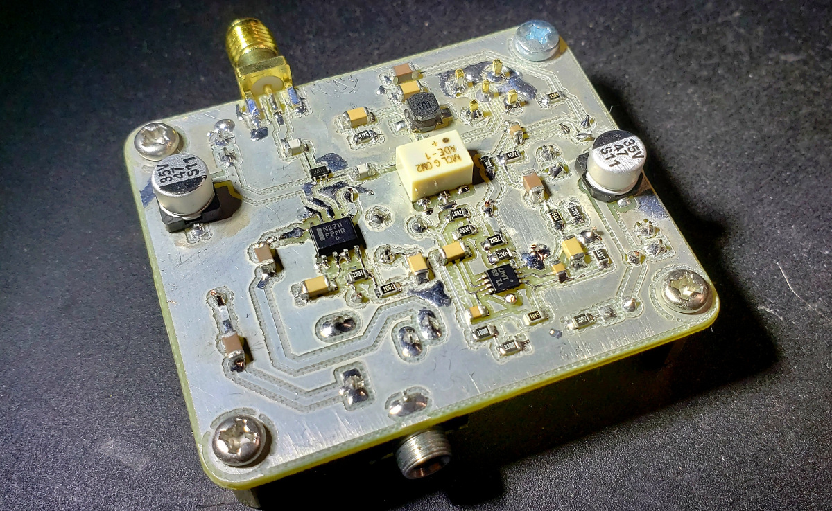
Construction
Assembly went well. I took some notes from how NA5Y puts his boards together, and did it one phase at a time. I started with the audio power amplifier, and worked my way back the chain until I had the whole thing put together.
I knew something was wrong as soon as I powered up the NCS2211 the first time. There was a lot of hiss! Lots of high frequency content, and crazy loud, even with the volume potentiometer pretty low. I have very little experience with audio circuits, so I really wasn’t sure if it was a problem – maybe it was just that I didn’t have any signal going into it? Hah, how naive!
Next came the opamps, with the bandpass filtering. I had added a testpoint where I could inject an audio signal here, before moving on to the RF components. And now I knew for sure I had a problem. The hiss was still there, though I could clearly see that the bandpass filtering was working. The peak was right around 650-700 Hz, just like I had planned. But the hiss…
I went forward with the rest of it: the BJT common base amplifier, the mixer, and the BGA2869 MMIC (what an adorable little thing to solder; glad I have the new microscope!). Strangely, the RF levels didn’t match what I expected – I had to put in just as much voltage as I had for the AF testing. So I knew there was something wrong there too.
So the result was a pretty board, but lots of issues. And I was very glad I hadn’t tried to build more that I had; this was enough to bite off and chew at one time! And in contrast with my Tayloe detectors, which were largely copied from other places, this attempt to build a simple direct conversion receiver was obviously going to teach me some new things. As Hayward, etc., had said in the books… I could see why this was a good rite of passage after all.
Fixing the Hiss
I posted my questions about hiss on the QRZ forum, and got some ideas from the magicians that hang out there. Though the solution wasn’t exactly what they said, their comments helped me find the answer, and I am quite grateful! The result becomes apparent if you look at the following three schematics:
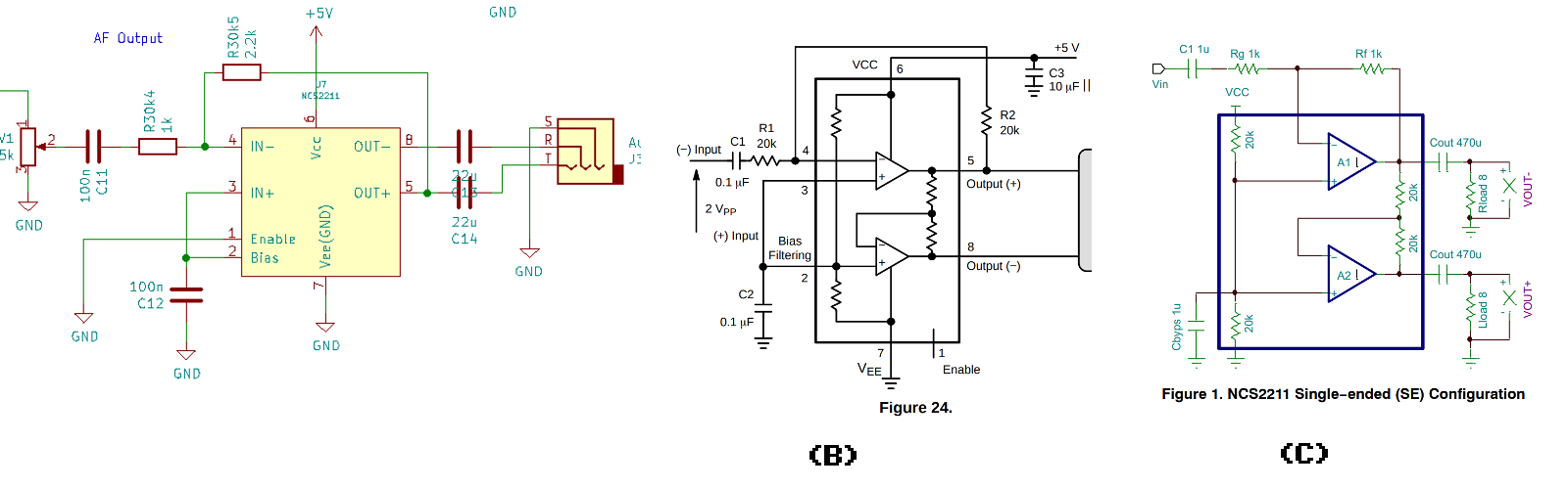
Schematic (A) is what I built, and (B) and (C) come from the NCS2211 datasheet and application note AND8467. Do you see what I did? I knew I had to do a single-ended version to feed a pair of headphones, but I had started with the reference schematic in (B). Along the way, making changes from (C) to make it single-ended, I thought I should add a little gain, and I chose values based on the input and feedback resistors (Rg and Rf in (C)). But, I didn’t change the values of the coupling capacitors, and that’s the first big problem.
The incoming coupling capacitor and the input resistor form a high pass filter, and its cutoff frequency with a 100n capacitor and a 1k resistor is 1592Hz! This means I was chopping off the low end, and pretty much all that was left was high frequencies. I swapped out the resistors for larger values (I believe the board currently has a 20k Rg and a 47k Rf, making an input high pass cutoff of 79Hz). This dramatically changed the character of the sound on the output, and it was much improved!
But it wasn’t perfect, there was still quite a bit of high frequency content. The next thing I did was add a feedback capacitor in parallel to Rf (I played with values from 1nF to 47nF, and I believe the current value on the board is 10nF). This presents a very low impedance to high frequency sound, which kills the gain, and makes things sound a lot better.
This experimentation helped me (A) learn some things about AF amplifiers, and (B) made me think a little harder about how I filter the signal going into the AF amplifier. E.g., I think the diplexer and common base amplifier have a very unsuitable frequency response, and need to be reworked. I’ve been studying other simple diplexers in preparation for an updated revision of the receiver.
Gain Issues
There was also not nearly enough gain in the system. For a time, I suspected the common base amplifier was at fault, but after breadboarding it and testing a good bit with a signal generator, and then matching measurements with the circuit on board, I ruled that out. It actually seemed to be working fine (though I have begun to doubt the truth of the LTSpice-inspired changes to achieve 50-ohm impedance).
So I turned my attention to the BGA2869. One comment the gentlemen on QRZ had made was that these are apparently finicky beasts – very sensitive to parasitic inductances, especially relating to the ground plane. Since my board is a single-layer affair, and has quite a poor ground plane (hey, I do what I can!), I started thinking my BGA2869 was writhing in a pit of self oscillation…
I bypassed the MMIC, and just attached the mixer to the SMA connector, and things got a lot better. The gain was pretty low, but I could at least prove to myself that RF was coming into the mixer, actually mixing (!), and coming out of the audio chain. I could hear pleasant beeps, and it was great!
So, what to do about that BGA2869? I get where the QRZ guys are coming from; it might just be a poor choice. But I was curious if I could get it to amplify something anyway. So while reading through the ARRL Handbook on handling parasitic oscillations, I was reminded that ferrite beads might be of help. If the oscillations can be damped by adding some impedance in the VHF range, perhaps it would return to proper amplifying duty? I happen to have a stack of 1206 ferrite beads, so I bodged them in. I’m simultaneously proud and ashamed of my flying ferrites:
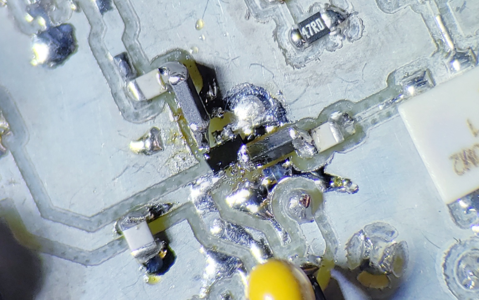
Yeah. So those big ferrite arches, tombstoning across the gaps, X-acto cut traces below… kind of like an anti-oscillation signal aqueduct. But… it worked great. Instant improvement; I could hear RF through the BGA2869, and with much weaker input signals, so amplification was happening. Yay!
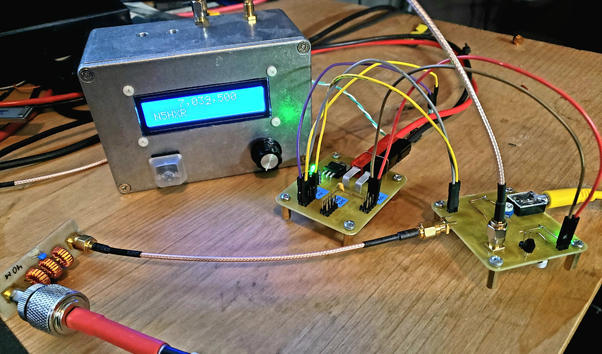
On Air Testing
I put this little guy up on my 84’ random wire, through a tuner of course, and spent some time watching signals through it. It just happened to be a CW contest that night, so I could tune around and catch quite a bit! I haven’t done any listening with a DSB receiver before, so it was neat to get the hang of identifying whether a signal was in the LSB or USB, and tuning around it. Sometimes, I could hear a signal in the LSB, but some loud signal in the USB got in the way… so I could tune down until I put it in the USB, and might have a clear LSB on the other side. So, no image rejection is obviously a pain, but I found the experience quite educational, and really, I could totally use it for making contacts if I had a transmitter to go with it.
For sensitivity, I thought I’d hook it up to my computer, and see if I could pull in some FT8. It did quite a good job for a Frankenstein hodge podge of misunderstood direct conversion ideas :-). Here’s a map of the grid squares I detected using FT8.

The next day, when daytime conditions were much less conducive to success (and there wasn’t a CW contest going on), I could see what was really going on. The sensitivity was quite unsatisfactory. Signals I know I should hear were quite dim, and A/B testing with another transceiver proved it quite handily. I dug out a little 60dB LNA board I had lying around, added 30dB of attenuation to it (gee, 60dB is a lot…), and the results were much improved. So clearly, for on-ear listening, I was about 30dB of gain short.
It’s worth a moment to reflect on why it worked so well for FT8, and not for the daytime listening. My computer’s soundcard has some substantial gain, and is quite sensitive (I’ve tested it before) as it is. It seems that the level of gain was perfectly reasonable for computer-based reception, since the sound card’s ADC was picking up the slack. Simple volume adjustment could account for the gain I didn’t have in the receiver. But plug in a headphone? Now I need a lot more gain!
This reminded me of my previous experiments with the Tayloe detectors. EMRFD says you need 90-100dB of gain to make a worthy direct conversion receiver, but I had gotten away with 60-70dB with my Tayloe detectors. I now see that this is largely because of the advantage of the gain capabilities of my computer’s sound card, and the additional challenge of raising the signal power up to the physically demanding task of moving actual speakers around. Cool!
Conclusions
So, in many ways I’m completely dissatisfied with this project. I messed stuff up, had to change and fix a lot of things, and even then it’s not really a good receiver.
On the other hand… man, I learned a lot. Tweaking the bandpass filters and fighting ringing and audio oscillations (oh, I guess I didn’t talk about that, oops…), understanding the NCS2211 circuit, fixing the BGA2869, re-simulating and even building the subcircuits off board to prove things to myself; it was all extremely valuable. I definitely know some things I didn’t know before!
I think I’m actually close to building a full, simple DSB transceiver. I’ve been building little one-off experiment circuits for a bit now, based on this project’s results, and I have almost all the pieces put together. The next few blog posts will probably be about some of those. I’m nearing a milestone: a complete, functional transceiver. Once that’s done, I can add image rejection back in, and throw in some DSP, and start after my real goal – digital modes.
Much fun had; much fun yet to be had!