A 60dB Attenuator
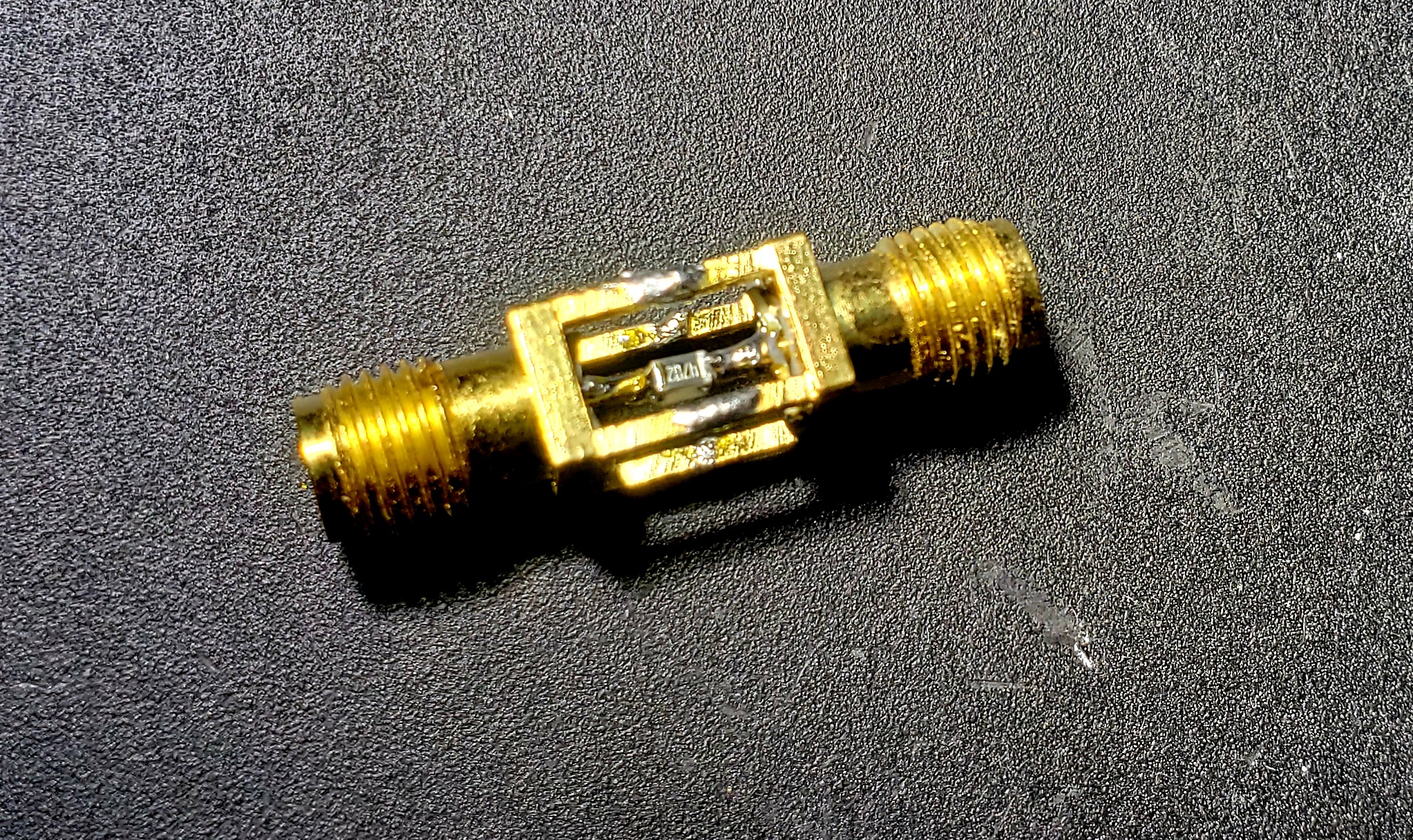
This is just a short little post, but I had to share. I suppose when one adds a binocular microscope to the home lab for building projects, one needs to find things to do with it. But this little project came out pretty well! I realized while testing my RF board in my last post that I just can’t make signals quiet enough to test receiver sensitivity. So I needed a big attenuator – here’s the result: a 60dB attenuator, in a svelte little package:
The Schematic
A Pi attenuator isn’t complicated, and it’s easy enough to find ideal values for the resistors. I did have to fudge some of the values based on what I had on hand, but it turns out to be close enough for the differences to be negligible:
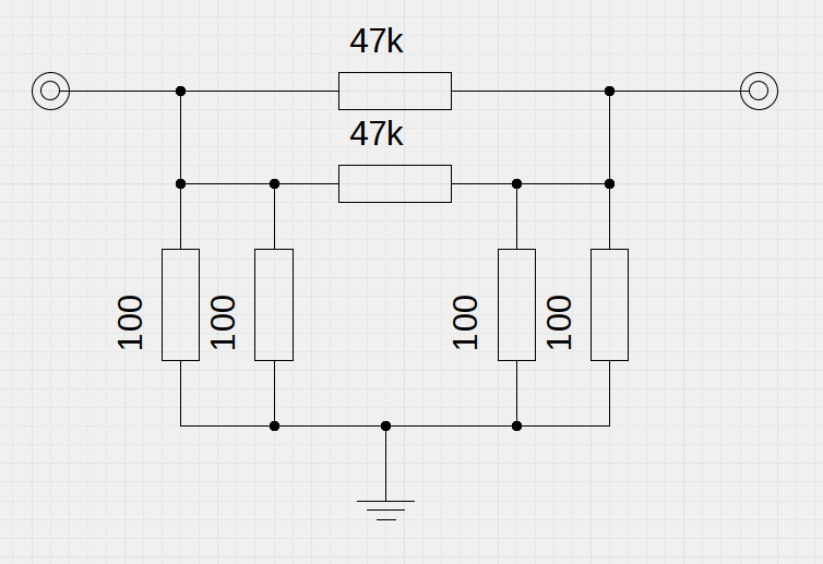
According to this calculator, what I’d really want is a series 25k resistor, shunted by two 50.1 ohm resistors. Easy enough to get quite close on the shunts with parallel 100-ohm resistors. But my series resistance is 23.5k, which is somewhat different. The calculator suggests I should see about 59dB of attenuation through it, and a 49.9 ohm impedance. Close is good enough in horseshoes, hand grenades, and attenuators. Or so I hope!
Construction
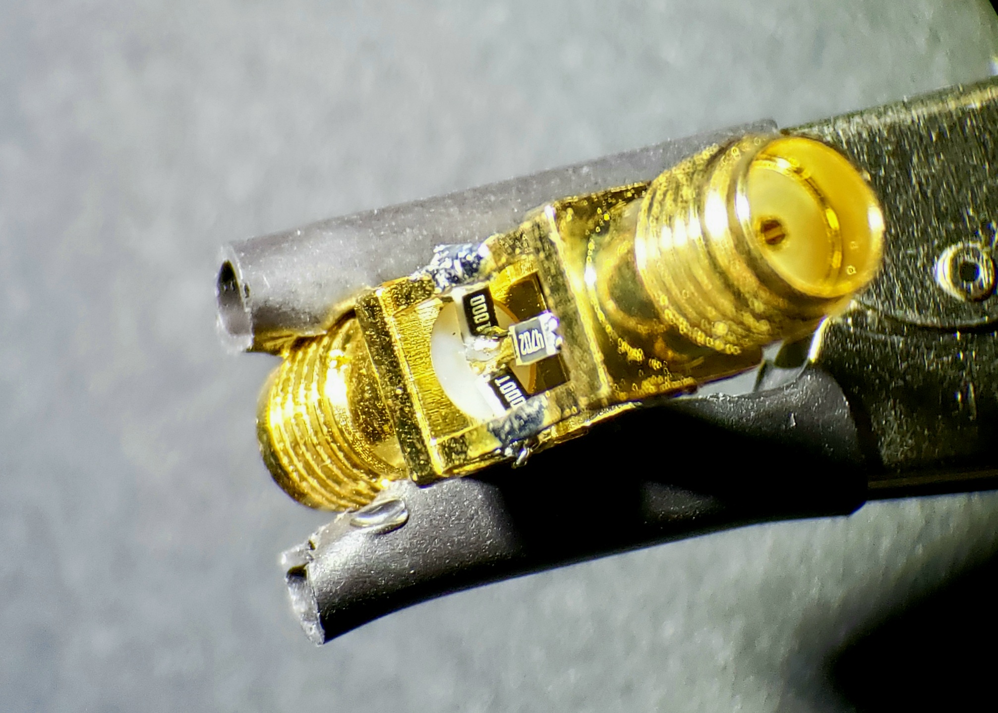
This was the fun part! I figured I could snip the center poles of two SMA connectors, solder the feet to each other, and bridge the gap with my 1% 0805 resistors. It worked great, though the microscope was absolutely necessary for making it all work out! These big brass connectors take a lot of heat, but enough flux, patience, and alligator clips, and it came out OK:
Testing
I calibrated the NanoVNA, and attached the attenuator. Here is the result:
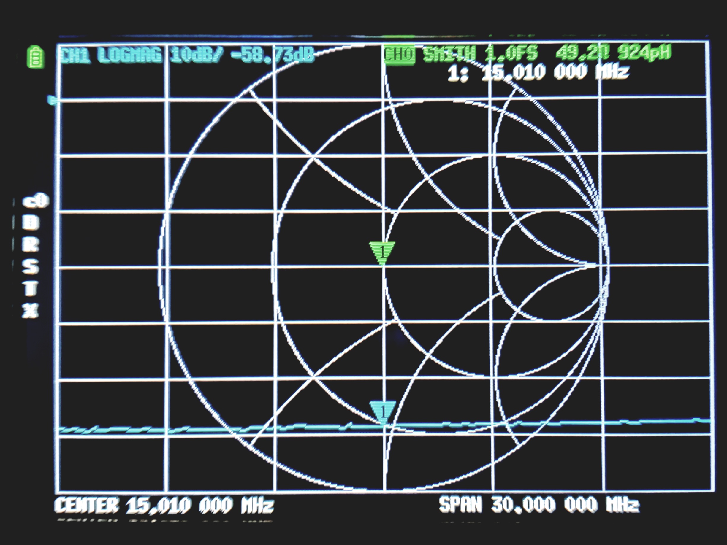
A nearly perfect resistive impedance, and hits about -58 to -59 dB of attenuation across the HF range. It does become somewhat inductive up in the VHF frequencies, but I don’t care much about that, as all my experimentation so far is HF only.
My signal generator can’t go smaller than 0.4mVrms, but with this attenuator I can take that down to microvolts, which makes testing some things possible. I set it up with the TinySA to see how tiny signals look. Here’s a 5.4mVpp signal from my generator, through the attenuator, and into the TinySA. It shows a -100dbM spike at 7MHz:
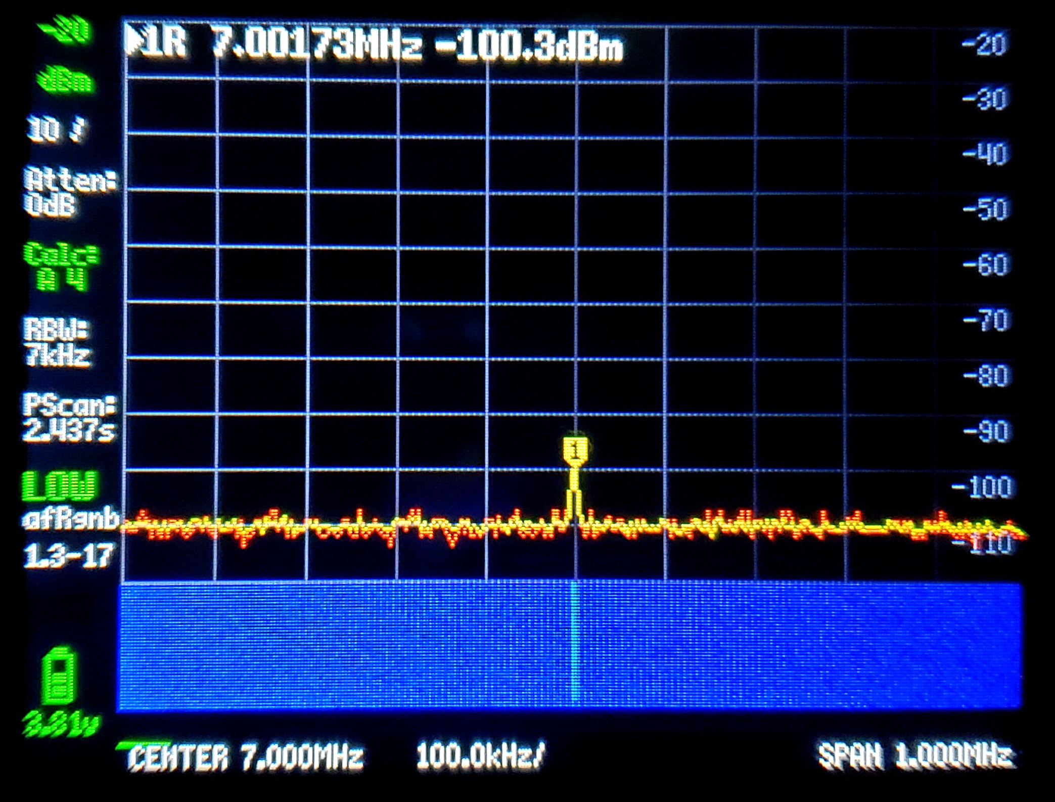
This seems to check out OK – 5.4mVpp is about 1.9mVrms, which makes for 7.3e-8W. Dividing that by 10**5.8 gets 1.16e-13W. Dividing that into 0.001W and taking the LOG base 10 yields 9.94 Bels; multiply by 10 gives me -99.4dBm. The TinySA says -100.3dBm, so I’m within 1dB of the expected value. Yay, it works!
Conclusion
So now I can make some very small signals, and get a better estimate whether my receiver boards can detect them. Also, building this is always fun, but it’s more fun with tweezers and a microscope :-).