Impedance Matching the IRF614 with the NanoVNA
I have been experimenting with the IRF614, which is off the beaten path for amateur radio power amplifiers. I was interested in some of the different specs from the IRF510, which is quite popular. Tonight I wanted to play with impedance matching, and see what difference a matched input would make. This blog post documents my experiment and my findings.
The Setup
I put together a very simple class AB power amplifier with the IRF614. Even though it’s built on a breadboard, I’m pretty impressed with what it has produced so far. The schematic is about like this:
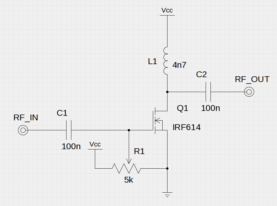
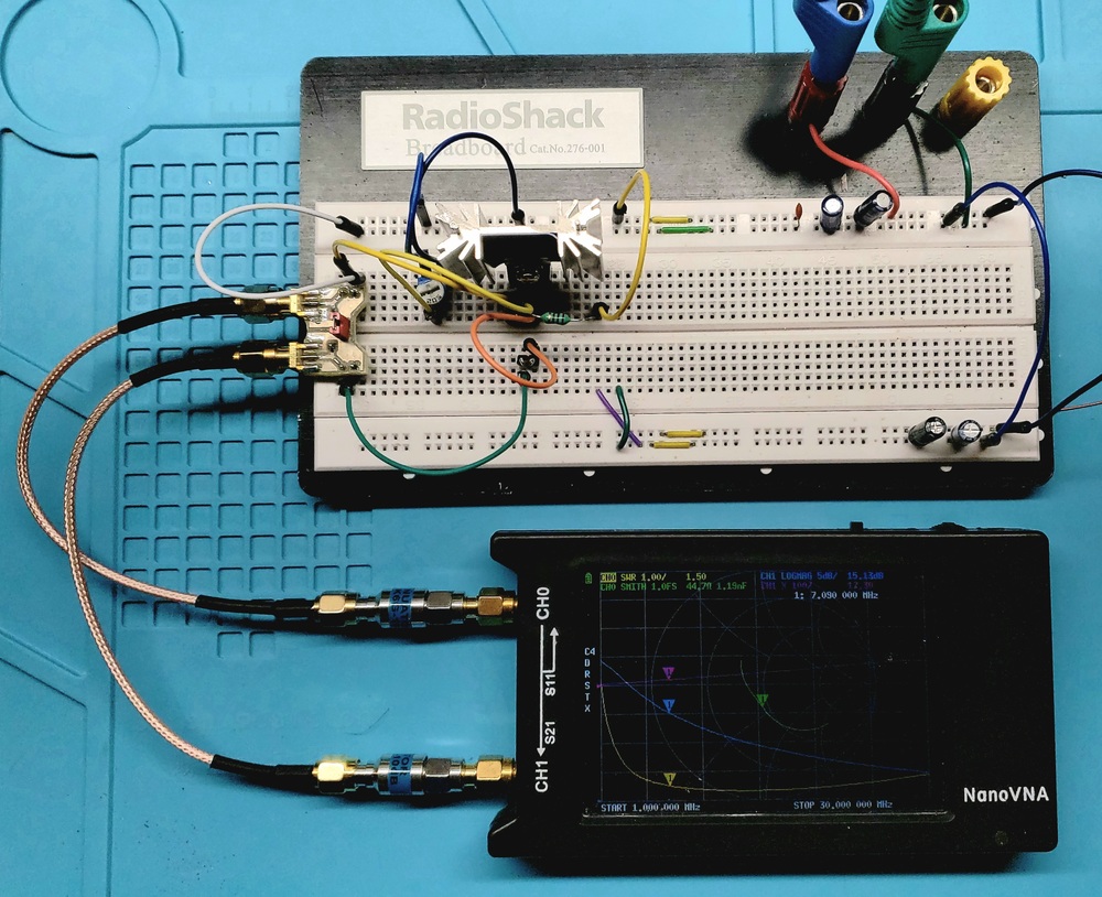
The biasing could be a little more sophisticated, but this turned out to be enough to play with for educational purposes. To round the whole thing off, there’s also an off-board 7th order low pass filter (cutoff about 8MHz, intended for the 40m ham band). On the bench, it ends up looking like this:
Measurements
I set up the NanoVNA for measuring the amplifier. There are a couple considerations that make this different from measuring other things. Mainly, the NanoVNA can be damaged if its output is amplified. I attached a 10dB attenuator to each port to make sure that loading and overall power levels would be kept within reasonable levels (you can see these in the photo above).
I then calibrated the NanoVNA at the ends of the cables (to remove the effects of the cables from the measurement), and attached it to the amplifier. With no changes from the above schematic, I saw the following output.
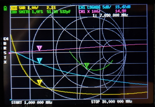
I don’t usually leave all the traces on (it can get kind of hectic!), but in this case I thought it was interesting to compare them. At the 40m band (7.09MHz at the marker), the SWR going into the amplifier was 2.23:1, and quite capacitive. More interesting, I suspected that simply adding a series inductor at the input could rotate the impedance up and clockwise, perhaps getting closer to a perfect match.
Matching
The NanoVNA said the impedance was 532pF capacitive. Using the formula 1/wC, this comes out to a reactance of about 42 ohms. Using toroids.info, I calculated that 16 turns on a T37-2 powdered iron toroid would be a pretty good match for that reactance, and perhaps cancel it out.
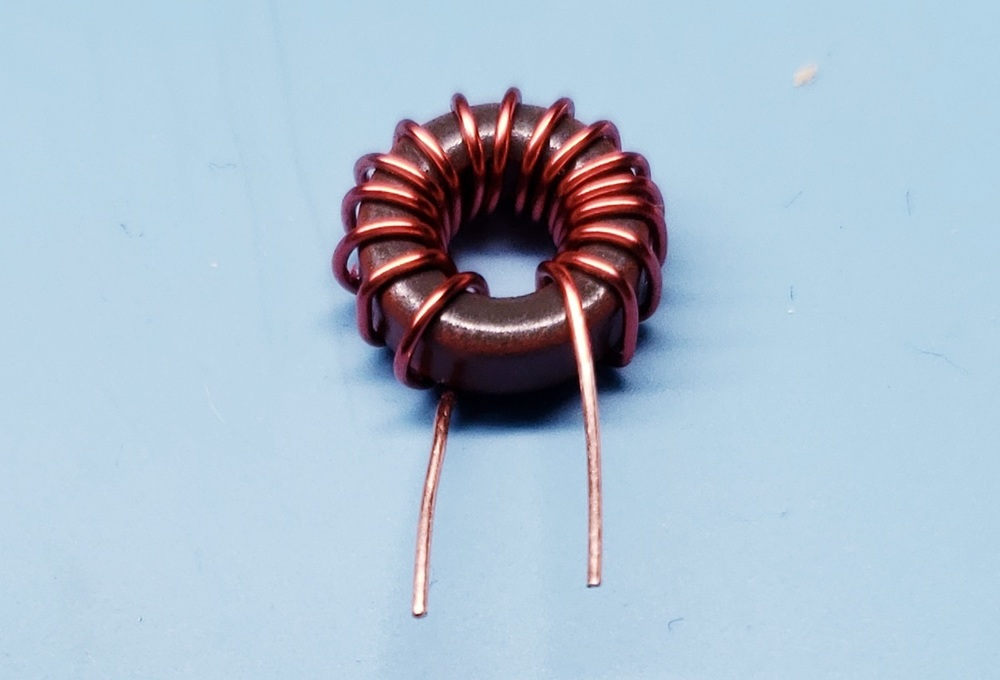
After putting it in series at the input (between the input coax connector and the coupling capacitor C1), the result was fantastic: 51 ohms resistive, and only a tiny reactance (0.9 ohms):
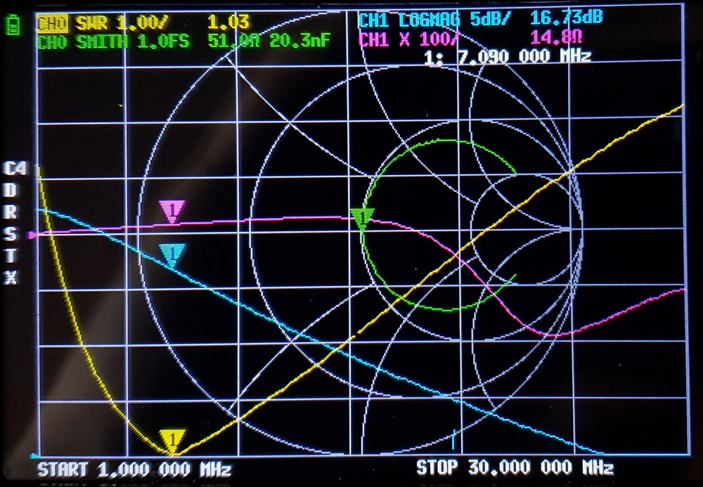
Notice in the screenshots that the total gain through the amplifier went up from 15.42dB to 16.73dB, simply by tuning the input for the test frequency. I thought that was pretty exciting – it made a bigger difference than I expected it to!
I compared results on the oscilloscope, to see if the NanoVNA was accurately indicating the increase in gain. It did indeed! However, when I added a low pass filter to remove harmonics, the difference in power in the fundamental was much closer. But, with the LPF the efficiency of the amplifier went up about 7%, resulting in less total power drawn from the supply.
Conclusions
By using the NanoVNA to measure the amplifier, and then use standard formulas to calculate the appropriate inductance to match the impedance, my confidence in the NanoVNA’s results has increased. I was also able to validate the behavior on my oscilloscope, for a little bit more confirmation.
I also got to play with the amplifier a little and watch changes on the smith chart. The small detail of trading gain for efficiency with the low pass filter by matching impedance was interesting, and I’ll continue ruminating on that.