Trusting the NanoVNA?
While working through some questions around impedance matching amplifiers, one of my mentors asked how confident I am in the measurements I get from the NanoVNA. I haven’t really run into a situation where it severely mislead me, but I had never really done anything to test its reliability. He suggested I measure a few values of resistors and capacitors and just check to make sure what we were seeing on the amplifier might be measurement error. That’s what this post is about!
I did some hasty measurements with a little jig I had rigged up before for attaching SMA connectors to breadboards. The results were encouraging, but a little questionable at times. So I decided I should build a better setup and be more rigorous about my testing.
Setup
I’ll be measuring complex impedances, and one of the biggest concerns is eliminating the influence of the test apparatus. If the connectors, cables, and attachment of components I need to test have parasitic reactance, it will spoil my measurements! Wires have inductance, connectors and cables have reactance, even the geometric arrangement of parts in space can cause problems. It was suggested that I attach header to an SMA connector, and components to small lengths of pin header. Here’s what I came up with for the measurement plane:
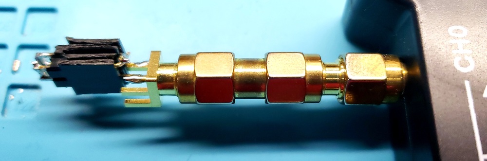
The connectors are somewhat unavoidable – I don’t have any SMA male connectors I could build this on at the moment. But this at least means there is no coax involved, and the influence of the male-to-male adapter and the header can hopefully be calibrated out. The following schematic describes what’s going on here:
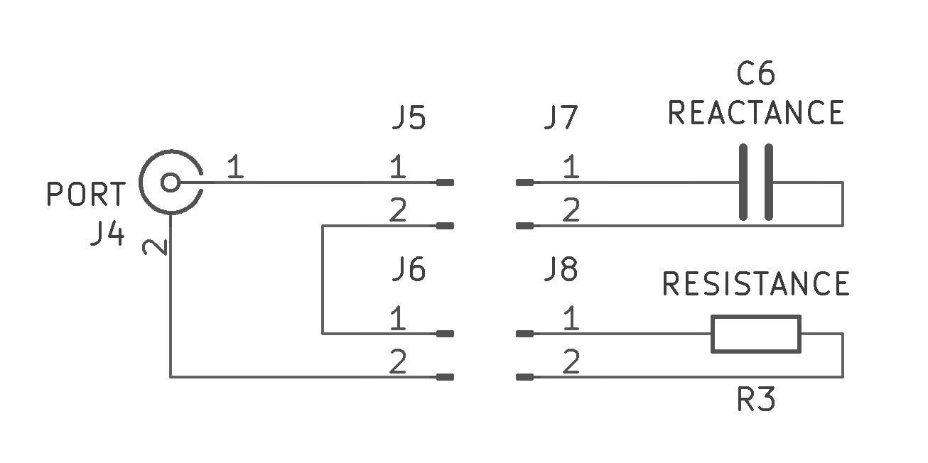
I can attach two components, each soldered to 1x2 pin header, in series to make measurements with the NanoVNA. In the picture above, you can (barely) see two “shorts”, where the pin-header pins are connected to each other, which I can use to calibrate for short circuits, or if I want to test just one component instead of two in series.
Next, I put together a bunch of components on pin-header of various values. Resistors are 10, 24, 50, 100, and 220 ohms, and capacitors are 22, 47, 100, 220, 470, 1000, and 4700 picofarads. I can mix and match these to measure different complex loads:
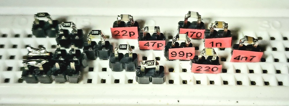
If you look closely, you might also see two pieces of 1x2 pin header that have nothing on them. Using these to calibrate for the “open” measurement, I can get as close as possible to a good calibration, with the measurement plane right at the components themselves!
Taking Measurements
I measured all of the components, by themselves and in series pairs. This gave me a pretty good survey of the bottom half of the smith chart, and I could see how the NanoVNA measurements varied from one configuration to the next. The result was quite accurate – more accurate than I expected, based on my initial tests. Here’s a table of all the results. All of this testing was at 7.0MHz.
| Resistor | Capacitor | SWR | Resistance | Capacitance | Inductance | Reactance |
|---|---|---|---|---|---|---|
| Ohms | pF | Ohms | pF | nH | Ohms | |
| 10 | 0 | 5.03:1 | 9.95 | 1.77 | 0.08 | |
| 24 | 0 | 2.09:1 | 23.9 | 1.28 | 0.06 | |
| 50 | 0 | 1.0:1 | 49.9 | 1300000 | -0.02 | |
| 100 | 0 | 2.0:1 | 100 | 86000 | -0.26 | |
| 220 | 0 | 4.42:1 | 221 | 14800 | -1.54 | |
| 0 | 22 | N/A | -4 | 22.5 | -1010.51 | |
| 10 | 22 | 1950:1 | 10.3 | 22.7 | -1001.60 | |
| 24 | 22 | 830:1 | 24.2 | 22.7 | -1001.60 | |
| 50 | 22 | 400:1 | 50 | 22.7 | -1001.60 | |
| 100 | 22 | 202:1 | 100 | 22.6 | -1006.04 | |
| 220 | 22 | 95:1 | 222 | 22.6 | -1006.04 | |
| 0 | 47 | N/A | -0.6 | 47.1 | -482.73 | |
| 10 | 47 | 460:1 | 10 | 47.5 | -478.66 | |
| 24 | 47 | 196:1 | 23.6 | 47.6 | -477.66 | |
| 50 | 47 | 94:1 | 49.5 | 47.6 | -477.66 | |
| 100 | 47 | 48:1 | 99.4 | 47.5 | -478.66 | |
| 220 | 47 | 26:1 | 220 | 47.2 | -481.70 | |
| 0 | 100 | 2050:1 | 0.523 | 99.2 | -229.20 | |
| 10 | 100 | 107:1 | 10.1 | 100 | -227.36 | |
| 24 | 100 | 46:1 | 23.7 | 100 | -227.36 | |
| 50 | 100 | 23:1 | 49.4 | 100 | -227.36 | |
| 100 | 100 | 13:1 | 99.2 | 100 | -227.36 | |
| 220 | 100 | 9:1 | 220 | 98.9 | -229.89 | |
| 0 | 220 | 58:1 | 5.4 | 197 | -115.41 | |
| 10 | 220 | 21:1 | 14.8 | 199 | -114.25 | |
| 24 | 220 | 11:1 | 28.3 | 199 | -114.25 | |
| 50 | 220 | 7:1 | 54.1 | 199 | -114.25 | |
| 100 | 220 | 5:1 | 104 | 197 | -115.41 | |
| 220 | 220 | 6:1 | 225 | 194 | -117.20 | |
| 0 | 470 | 124:1 | 0.8 | 456 | -49.86 | |
| 10 | 470 | 10:1 | 10.1 | 458 | -49.64 | |
| 24 | 470 | 4.4:1 | 23.8 | 458 | -49.64 | |
| 50 | 470 | 2.6:1 | 49.8 | 456 | -49.86 | |
| 100 | 470 | 2.6:1 | 99.9 | 452 | -50.30 | |
| 220 | 470 | 4.7:1 | 221 | 440 | -51.67 | |
| 0 | 1000 | 57:1 | 1.06 | 950 | -23.93 | |
| 10 | 1000 | 5.7:1 | 10.7 | 949 | -23.96 | |
| 24 | 1000 | 2.6:1 | 24.6 | 946 | -24.03 | |
| 50 | 1000 | 1.6:1 | 50.7 | 941 | -24.16 | |
| 100 | 1000 | 2.2:1 | 100 | 928 | -24.50 | |
| 220 | 1000 | 4.5:1 | 221 | 881 | -25.81 | |
| 0 | 4700 | 192:1 | 0.26 | 4540 | -5.01 | |
| 10 | 4700 | 5:1 | 10.1 | 4570 | -4.98 | |
| 24 | 4700 | 2.1:1 | 24 | 4550 | -5.00 | |
| 50 | 4700 | 1.1:1 | 50.1 | 4500 | -5.05 | |
| 100 | 4700 | 2:1 | 100 | 4280 | -5.31 | |
| 220 | 4700 | 4.4:1 | 221 | 3500 | -6.50 |
Conclusions
The NanoVNA was generally quite accurate, and moreso the closer on the smith chart that the load was to the center. I did observe some reduced accuracy close to the edges of its ability to measure. But for the large part, capacitance and resistance measurements were accurate within a couple percent. For each capacitor value, I calculated the coefficient of variation (CV) of the capacitance measurements, which gives a sense for how repeatable the measurements are with varying resistance values:
| Capacitor | Cap. CV |
|---|---|
| 22pF | 0.4% |
| 47pF | 0.5% |
| 100pF | 0.5% |
| 220pF | 1.1% |
| 470pF | 1.5% |
| 1nF | 2.8% |
| 4.7nF | 9.6% |
Note that the variability increases as the reactance becomes more negligible – the 4.7nF capacitor barely contributes to the load’s impedance, and I guess the measurement is near the limit of the NanoVNA’s capability. It is exactly this region that is probably least important, as in most cases getting close to zero reactance is “good enough”.
If using the NanoVNA to measure an unknown reactance, this variability at the edge of the measurement range can be compensated for by just changing the frequency of measurement. When I switched to 1MHz, the 4.7nF capacitor measurement became more reliable. For measuring an impedance at a frequency you care about, perhaps the fact that the contribution is negligible at the fuzzy edge is some consolation.
There is also an interesting anomaly with low resistance – the 10-ohm resistor in series with a 220pF capacitor showed a resistance measurement of 14.8 ohms. It’s off by 48%! It’s the only case where this happens, and I’m quite puzzled why. The capacitance measurement is still correct.
Ultimately, being generally within a few percent of actual values is quite satisfactory – this testing has increased my confidence in the NanoVNA. Though, for testing at the extremes of the smith chart, I do wonder if someday I’ll be buying a fancy VNA.