Digital IQ Modulation
I was greatly inspired by this video from W2AEW, where Alan shows the use of an IQ modulator to generate amplitude and phase modulated signals. I’ve enjoyed playing with simple FSK modes, using an Si5351 and changing its frequency to modulate data (played with Hellschreiber, WSPR, and RTTY, for example). But the idea of trivially generating PSK and QAM signals with a couple of mixers was intriguing.
This blog post is about my initial adventure, building an IQ modulator, playing with it, and making some enhancements…
This project really got started when I was looking through a box from Mouser, and stumbled onto a bunch of NC7SBU3157 analog switches. I forget now why I had bought it, but having just watched the video from W2AEW, I wondered if I could use these fast little switches to make an IQ mixer. The idea would be to flutter the switches at some RF frequency, and chop up some DC voltages into an RF signal.
IQ Modulator
Assuming I have a suitable quadrature local oscillator, I worked up the following schematic:
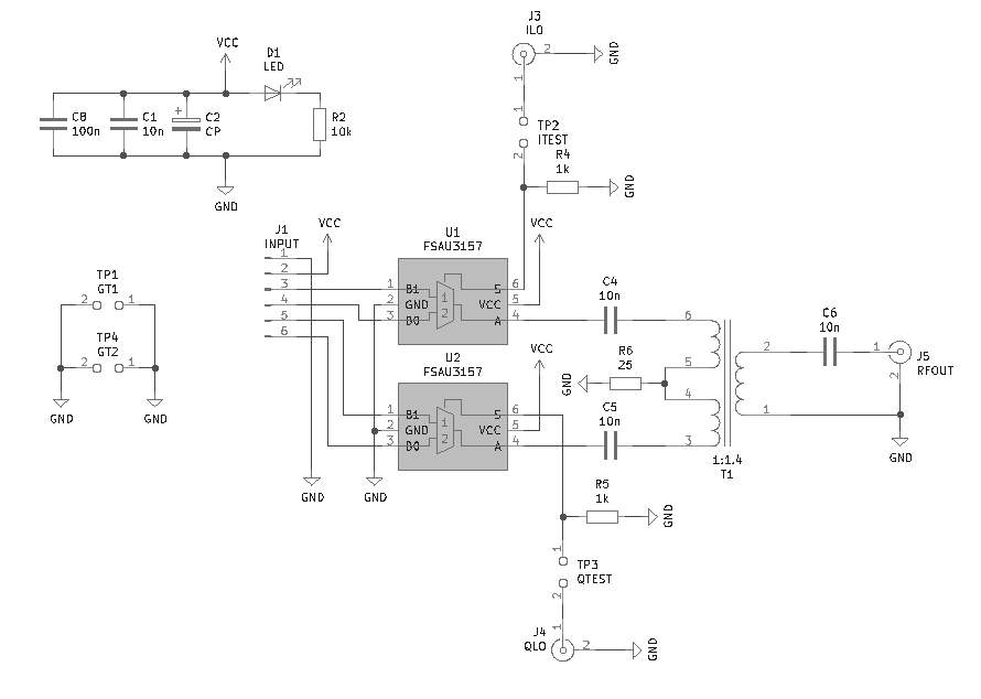
The local oscillator signals enter at J3 and J4, flipping the switches rapidly. Through the RF combiner at T1, each input leg to the combiner is alternately exposed to the voltages at the inputs to the switches. If these voltages are the same, then there is no contribution to the output from the combiner. But as the voltage between the two switch inputs increases, there appears a growing square wave at the frequency of the switch flipping.
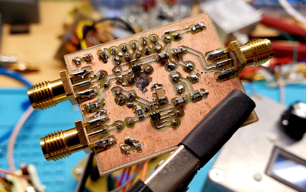
Assembly went quite smoothly. I’m either getting better at planning and building things, or I was lucky; there really weren’t any errors that got in my way on this one! I didn’t tin-plate the copper, so soldering was a little less fun – but that’s mostly just a reminder of why I like to tin-plate anyway. And yes, those little switches are tiny in their SC-70-6 package!
Initial Testing
For the local oscillator, I pulled my QRP Labs VFO kit off the shelf – it can generate two signals in quadrature from the 80m band through the 2m band. It’s a 3.3v square wave, so it should work well with the logic levels on the NC7SBU3157s. Finally, I rounded things off with a little power supply, and a low pass filter.
Starting simply, I thought I’d just connect all of the inputs to ground, and connect one at a time to a supply rail. That way, either I or Q would be “on”, and the phase should just flip depending on which of its inputs is positive. This worked wonderfully, producing what I think might be one of the prettiest oscilloscope traces I’ve ever made:
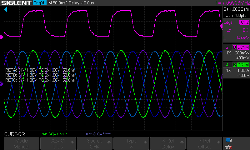
With just one pin high at a time, I can create four different phases on the output. I could just imagine each one being a symbol, and toggling the values to modulate some binary data. These are the building blocks of QPSK, and I was really excited to see this work so cleanly on the first try.
Modulating Some Data
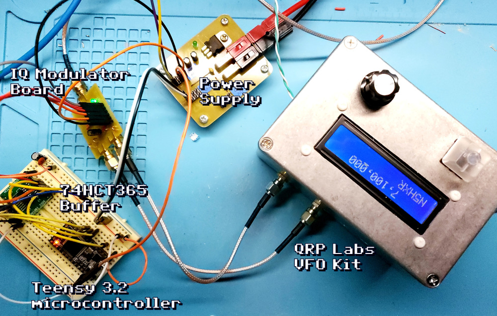
OK, proving the concept is something, but how about if I could send some data? I imagined perhaps I could just set the inputs with GPIO pins from a microcontroller… Since I wasn’t sure about current limits on the pins of my Teensy 3.2, I thought I’d buffer them with a hex buffer I had lying around (74HCT365). Each pin can source or sink about 20mA of current, so I thought that might give me some reasonable levels for testing.
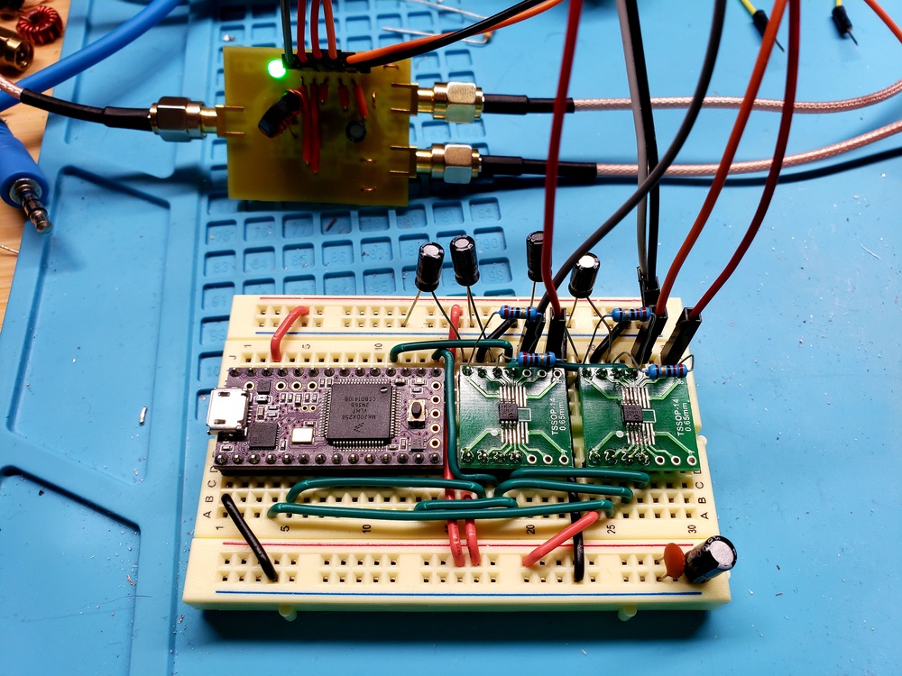
With a power supply, and a bunch of jumpers, I came up with this arrangement of the hardware (the 7th order low pass filter is outside of the picture):
If I set both I and Q with logic low and high on their input pins, they will add in the combiner for a slightly higher voltage, and phase right between them. If I flip the inputs in each pair, then the I and Q signals will flip 180-degrees, and add to the opposite. This should make for binary phase shift keying (BPSK) – I immediately thought of PSK31, a popular digital mode that uses that modulation. But how hard might it be to implement?
I reviewed the PSK31 spec, and was surprised how simple it is. When transmitting, a 0-bit is signaled by flipping the phase of the carrier; a 1-bit simply stays the same. This is differential BPSK, which means you don’t have to establish which phases are which bits (and also means you can tolerate ionospheric phase hijinks, doppler, jitter, and all kinds of other real-world annoyances). The actual bit stream in PSK31 is a varicode, where every character is a series of bits, but never with two consecutive 0-bits (those are spacers between characters).
All told, the code to transmit my callsign in a loop, with 5 seconds break in between, came out to this very simple Arduino sketch:
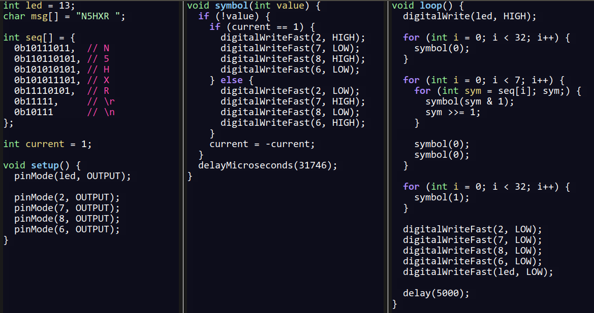
While sticking out my tongue at the right angle, and squinting (just a bit, I did have a current limit set on the power supply!), I flipped the switch, and was excited to see a bunch of RF. Zooming in, I could see that the phase would flip sometimes between bits – this was very encouraging! Unfortunately I didn’t snag a screenshot from the oscilloscope, but it was easy to verify the phase shift by measuring with the cursors.
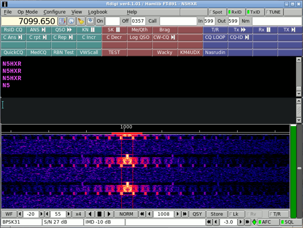
I wondered if my FT-891 could pick up the signal, being in the near field. I was dumping the output from the modulator into a 50-ohm dummy load, but I expected it should be loud enough a few feet away… I turned on the radio, tuned around, and was greeted by what actually sounded like the warble of PSK31. I started FLDIGI, and found that I had nailed it: my callsign decoded just fine!
Yay! But wow, look at those keying sidebands. With this hard keying between phase shifts, things were kind of bad. Here is what it looked like on the spectrum analyzer (eek!):
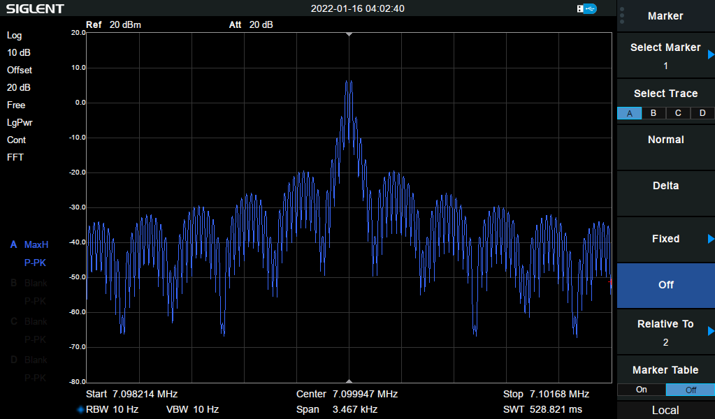
This is why “proper” PSK31 does raised-cosine envelope shaping on its output. Before flipping phase, the amplitude of the signal gracefully curves down to zero, the phase flips, and it gently comes back up to full strength. I wondered how I might be able to tone down the key clicks. My first thought was to apply a little filter to the inputs to the modulator – just a big capacitor and a small resistor… it helped a bit, but not much:
Still, things improved, so shaping the envelope should improve things. There was simply nothing else to do, I had to order some DACs!
Amplitude Control
Our story picks back up after the brown truck of happiness has delivered me a handful of MCP4082 DACs. These are little 8-bit DACs with opamp buffers whose specs suggest they should be able to source and sink current slightly better than my hex buffer. And they should be configurable for 256 voltage levels from 0 to 2.048 volts. I couldn’t wait to change everything up and try it out.
I read up in the datasheet how to control the DACs. They use SPI, and it’s a simple 16-bit transaction any time I would want to change the output value. But, my first couple attempts to set the values didn’t work… it took some experimentation to work out what needed to be done. This is one more time I’m glad I bought the Siglent, as it came with SPI decoding features enabled for no extra charge. Here’s a little shot of everything working:
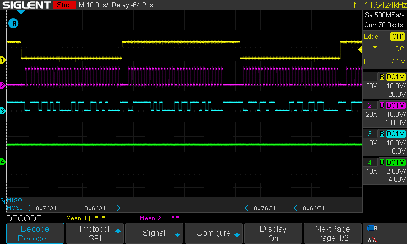
The main issue was that I had to set the SPI bus to operate in SPI mode 0 (this has to do with the timing and polarity of signals on the SPI bus). Once I set that correctly, I was good to go!
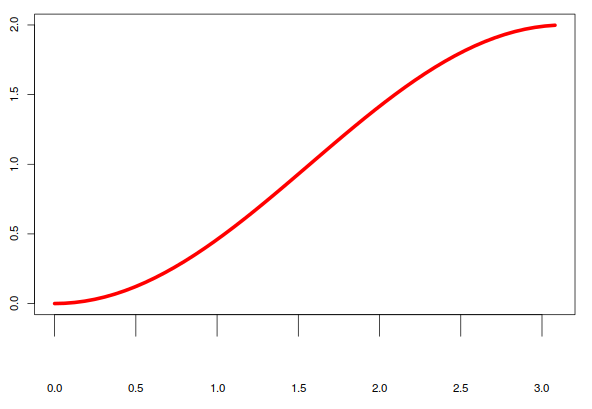
Now I had to figure out how to make that raised cosine shape. I dinked around in GNU R for a bit, and worked up the following curve. It seems to have that graceful rise and slows down at the peak, just like it’s supposed to (it’s y = 1 - cos(x)):
For reference, the way I calculated the values for my 8-bit DAC is as follows (at the GNU R prompt):
> x <- seq(0, 50)
> xs <- (x / length(x)) * pi
> plot(xs, 1 - cos(xs), type='l', lwd=5, col='red')
> floor((1 - cos(xs)) * 64)
 [1]   0   0   0   1   1   3   4   5   7   9  11  14  16  19  22  25  28  31  35
[20]  39  42  46  50  54  58  62  65  69  73  77  81  85  88  92  95  99 102 105
[39] 108 111 113 116 118 120 122 123 124 126 126 127 127
>
Starting at 128, each DAC output uses these values, one increasing, and one decreasing, to ramp up a signal. Just go backwards to bring it back down.
This code worked great. I had to add a little low pass filter on each DAC output (a 22-ohm resistor over a 10uF capacitor) to stabilize the values. And it took a few times back and forth to work out the timing to match PSK31’s 31.25Hz, but the result was this – another beautiful oscilloscope trace! (Actually, I’ve never made keying waveforms as pretty as this before, wow!)
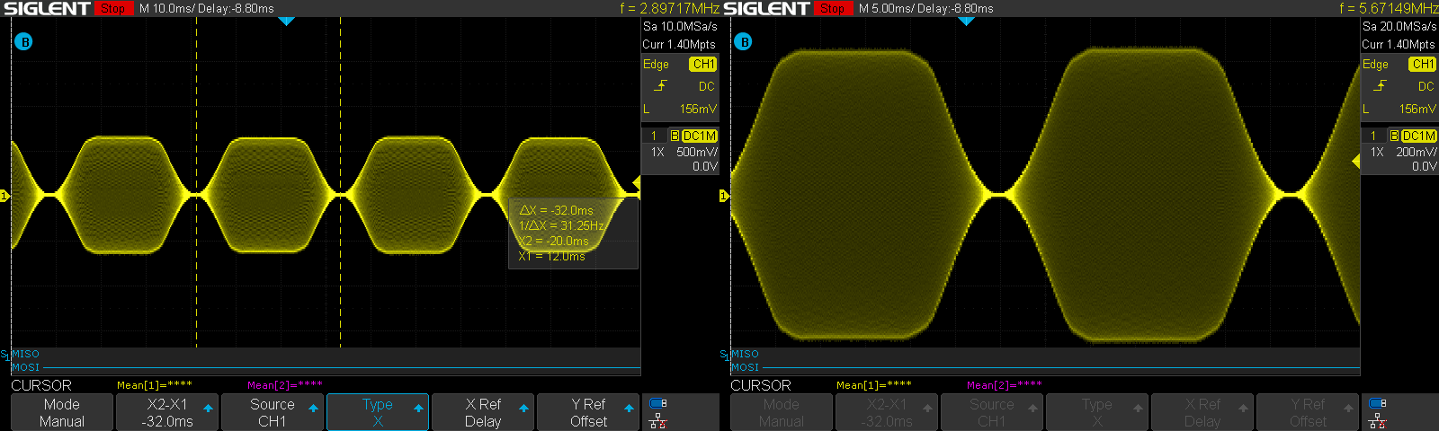
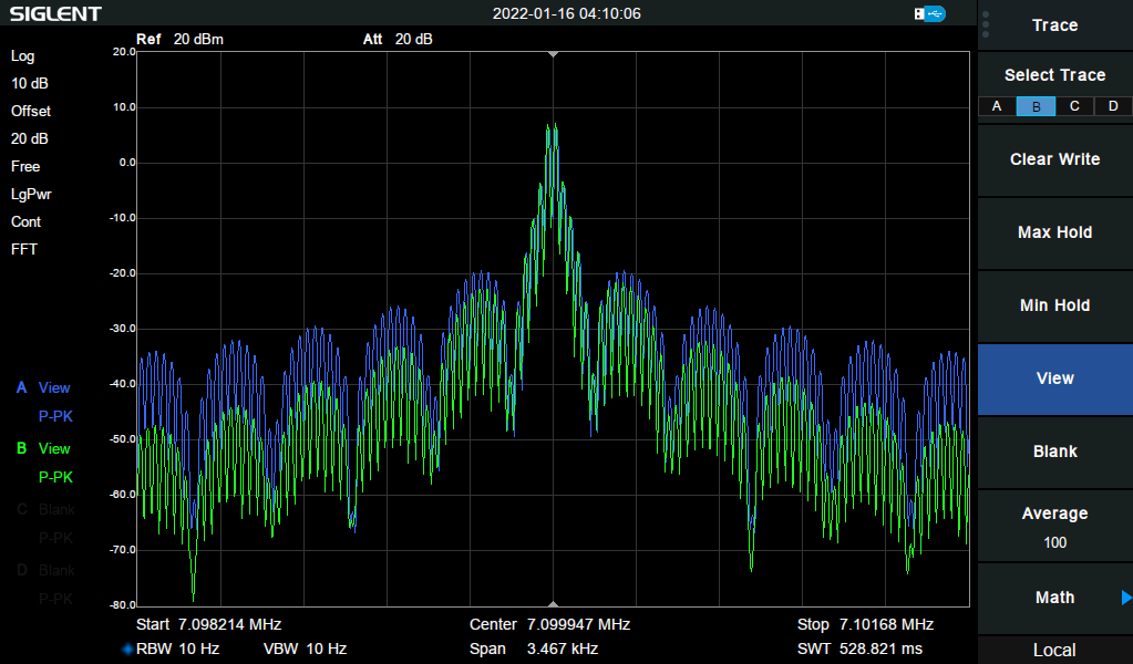
But how would this look on the spectrum analyzer? I set things up for the same kind of test as before, and the difference was amazing. The raised cosine envelope is definitely worth it! The left is the original hard-keying signal, and on the right is the raised-cosine version:
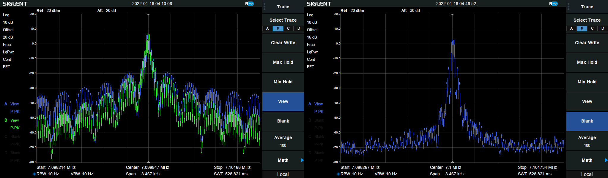
Further, I checked on a receiver, and could definitely tell the difference with and without the raised cosine envelope. Key clicks were detectable quite far from the carrier frequency with the hard keying, and were essentially non-existent in the latter case. Wonderful!
For the final test, I thought I’d connect the output of the modulator to one of my RF power amplifiers. This is just a simple IRF510 in class AB. The result was a surprising 250mW of output – and furthermore, the trace looked like an exact reproduction of the keying waveform shown above (just MOAR POWER!).
Conclusions
I’ve mostly been playing with nonlinear amplifiers and modes thus far, and using cheap QRP tricks to kill key clicks. Seeing all this linearity work and pay off so well was really amazing. I’ve been hoping to get back to digital modes in my experiments, and still have a dream of building a little homebrew digital transceiver that I can use to do a POTA activation (be the change you want to see in the world, etc.). This week’s experimentation is really encouraging in that direction.
Up next, I’ll play with demodulation – there are a couple strategies, and hopefully I can work out an effective approach there. Making things work is fun!