Si4467 Dev Board
I’ve been playing with some different attempts to venture into the VHF and UHF bands (in terms of homebrew projects), and hit a lot of dead ends. This post is my first real success getting something going on the 70cm band, playing with Silicon Labs’ Si4467 chip.
How I got to this point
I’ve done a lot of HF projects, as should be evident from the posts here. And HF is really fun, don’t get me wrong! But part of my goal in this whole journey is to work my way up the spectrum and (ultimately) achieve some level of capability in general RF engineering. As such, the VHF barrier has loomed ahead of me for some time. There’s a lot I don’t know, but I started wondering if I’d cut enough teeth on HF to venture a bit higher…
I tried playing with the Si5351 on the 2m band, but it proved to have pretty bad performance. Phase noise and other problems would make it a pretty bad citizen on the band, and after reading that a lot of other people felt the same way, I decided it wasn’t the best way to go.
My first real attempt was to make a discrete oscillator – I don’t think I have any photos, or even a schematic for it, but that didn’t go so well. I stumbled onto the MAX2607 VCO from Maxim, which is a little voltage-controlled oscillator. I rigged it up on a homemade board, configured for the 2m band:
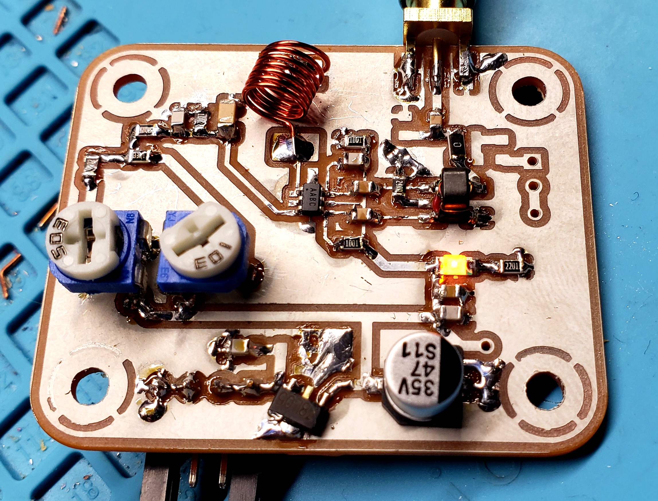
It did work, but there was an obvious problem right away. The output was very clean (in terms of harmonics and spurious output), but it was not very stable. Just watching it on the spectrum analyzer, I could see it wobble all over the place. And if I moved the board, or just approached it with my hand, it would detune and go somewhere else… Here it is wobbling around a ~15kHz zone in a period of 10 minutes:
It turns out these VCO chips are designed to be used in a more complex arrangement, with some feedback loop disciplining the output (e.g., a phase locked loop, or PLL). They’re nice and cheap, but not a complete solution, alas!
So I need a PLL
After some investigation of crystal-based oscillators for VHF (typically some HF VCXO through a few stages of multipliers), I decided I really wanted to find a PLL solution that would work. It should give me the most flexibility for a lot of different kinds of projects, and is certainly the most common approach in commercial equipment anyway.
But PLLs for VHF get kind of interesting. I consulted with some of the wizards on QRZ and a few other places, and the recommendations sort of stabilized around Analog Devices’ line of PLL chips. With all the myriad options for PLL configurations, performance metrics, and design parameters, it was pretty confusing! Someone pointed me to ADIsimPLL, which certainly helps out in simplifying the design process. You can choose a PLL chip, specify frequencies and channels, bandwidth, etc., and generate a likely solution.
But… as I mixed and matched and played with the software, I would sketch things out, and there was one clear issue. I want to build a bunch of projects, but the price of these PLL solutions was getting pretty crazy. I saw I could build something on the ADF4002, which is a $6 chip by itself. But then I might need to add a prescaler, parts for the loop filter, the reference, etc. Or, I could cut some of that out with a chip that had more parts built in, but pay double or more for the chip. With numerous sketches, I realized I can’t build a PLL for VHF/UHF this way for less than about $15 in parts (maybe $10 with compromises).
With the LO being only one component of a build, that really raises the cost, board space, and complexity of projects. I could see doing it a time or two for self-education, but ultimately getting frustrated with the price.
Why, I wondered, isn’t there a VHF/UHF equivalent to the Si5351? A $2 chip that generates a decent, frequency agile signal that I could use as a building block in other projects in the future?
Finding a chip
Looking through Mouser and Digikey at clock generators and oscillators, I found a few single-frequency options. I thought I could use a mixer to make a VFO out of one of those and an Si5351, maybe. It would also need an amplifier to get a useful output level… it becomes less interesting pretty quickly, so I moved on. Trying to keep the price anywhere near the $2 zone just leaves very few options. And some that exist don’t have the best parameters for use as an RF generator.
I briefly entertained using some of the little key-fob transmitters, which exist in the 70cm range. These are actually really interesting possibilities like the MICRF112 and similar. They’re super cheap (less than $1!), and come with a few different approaches for tuning, and emit a CW output at usable power levels. But… when I asked one of my mentors about it, he said, “No, don’t use those!”
Why? I had to learn about phase noise metrics. Most of these little transmitters are absolutely awful! E.g., within a channel or two on the 70cm band, they’d be -70dBc, which is very bad band citizenship. They’re only appropriate for very low power and infrequent, brief use.
But that got me thinking… what other families of fully integrated transmitters might there be? Shouldn’t there be another quality level step up? And that led me to some real success!
Several manufacturers make lines of little RF digital transceiver chips. E.g., the CC1101 from TI has been used in a few projects in the hacking community (e.g., the Flipper One). It’s phase noise is much better than the key fob transmitters, but still nothing to write home about.
But that gave me hope, and I eventually stumbled on the Silicon Labs 446x series. There are a few pricing levels, and several different capabilities (e.g., 2FSK vs 4FSK, etc.). These chips do CW, OOK, FSK, etc., operate from 142-1050 MHz, and have reasonable phase noise performance. So I decided to build up a dev board with the Si4467 and play around with it!
Designing my first UHF board
Silicon Labs publishes a lot of documentation for these chips, with some reference schematics, and guidance on matching networks, etc. Since their primary market is ISM devices, though, they don’t publish much material that would be relevant to the 2m band. But, they do provide specific guidance for the 433MHz ISM band that exists in Europe – since that’s the 70cm band, I decided to take the leap all the way to UHF!
I used the datasheet and some of the application notes to put together a basic reference schematic for the chip:
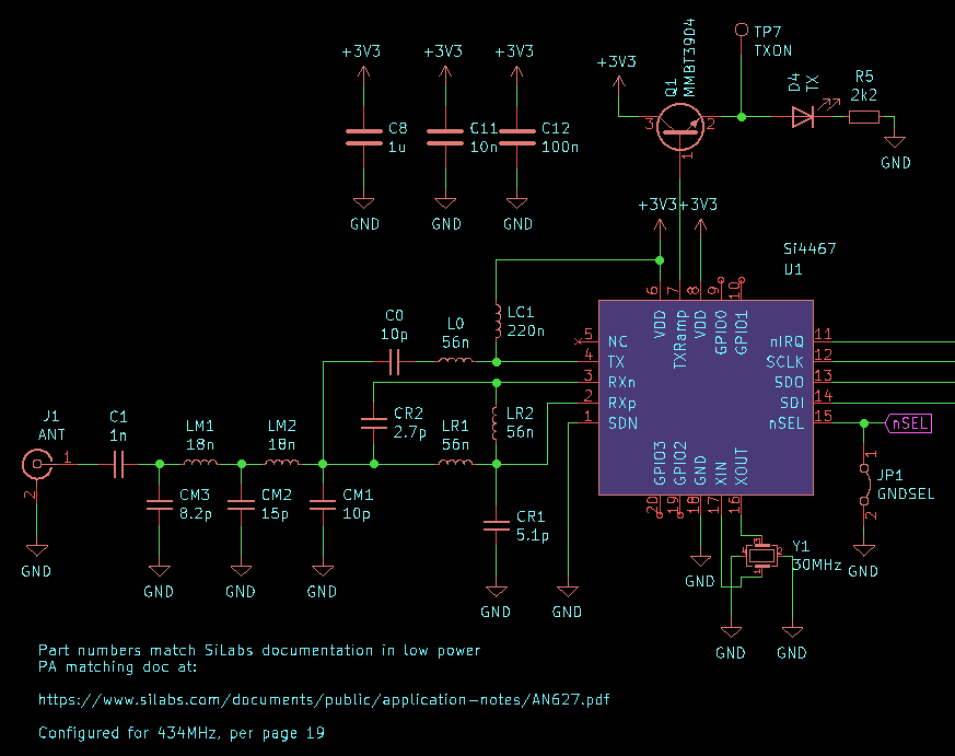
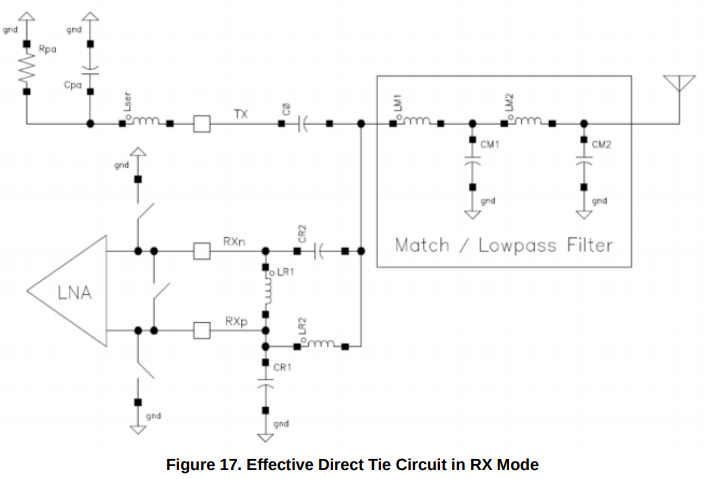
The output from the chip is very interesting. There are three things going on here. First, there is a resonant tank for class-E operation. Second, there’s an impedance matching output low pass filter that loads the chip properly for 13dBm output power.
But there’s some interesting stuff with LR1, LR2, CR1, and CR2. This is what SiLabs calls the “Direct Tie” configuration, where the RX and TX pins are connected to the same antenna, with no switching involved.
These components are a balun, of a type I’d never seen before. This configuration splits the RX input to two signals that are 180-degrees out of phase to provide a balanced input to the RX pins. What’s even cooler is that the TX/RX switching in the chip grounds CR2 and LR1 in parallel, creating a tank circuit that blocks the TX signal when transmitting, protecting the RX circuitry. Here’s what it looks like, per SiLabs’ documentation:
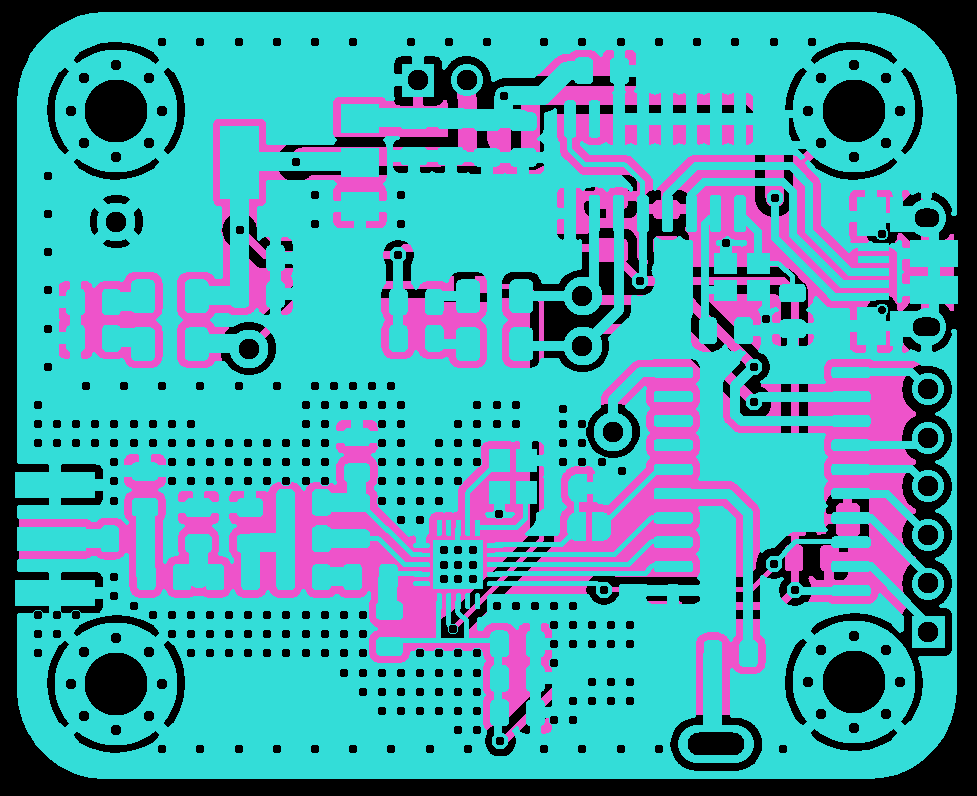
There’s also a lot of guidance for component placement, routing, and ground planes, so it wasn’t too hard to put together the PCB design. Lots of via curtains and stitching, and I kept everything pretty close together. I took a bit of a risk and designed it for 0805 component sizes. The SiLabs reference values for the matching networks are for 0402 sizes, and I hoped that it wouldn’t make too much of a difference. I don’t like working with 0402s (I bottom out at 0603s, usually).
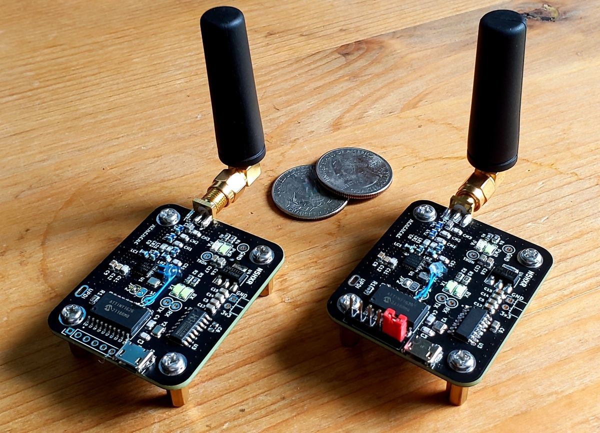
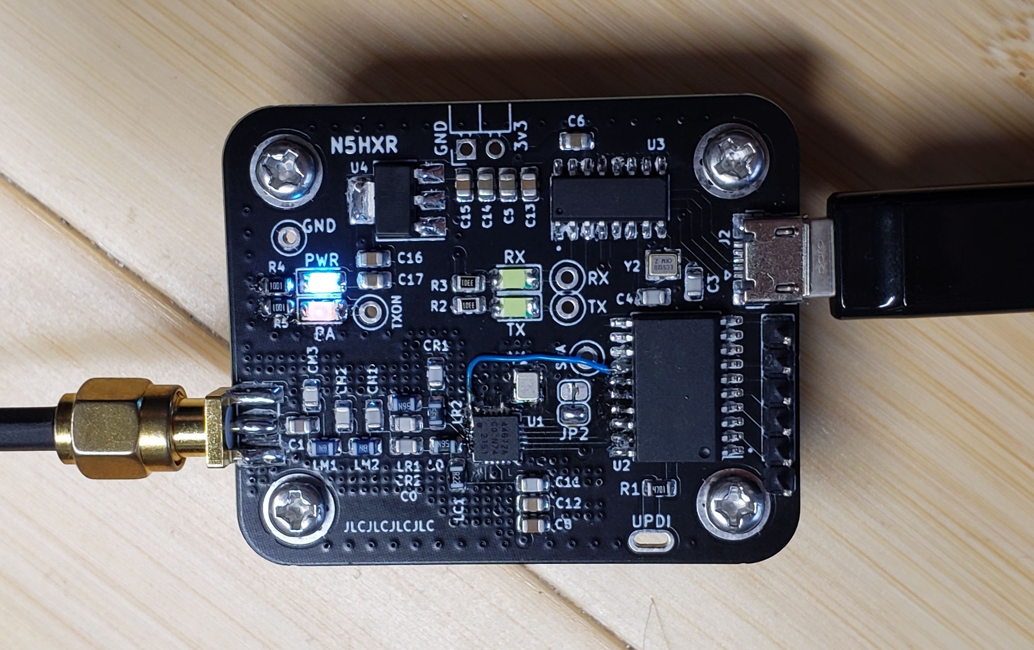
The board includes the Si4467, its matching networks, an ATTiny1626 microcontroller, and a CH340G USB serial chip. I figured if it worked, it would be a fully self-contained solution I could use for a bunch of projects.
I ordered some boards and a stencil from JLC PCB. I sprung for the stencil because of the packages. The Si4467 is a QFN20, which is a bit annoying to do by hand (could do it with air, but I rather like the hot plate I’ve been using lately).
Everything arrived, and assembly went pretty smoothly.
Initial testing
Everything passed basic continuity probe tests, so I powered it up… and thus began the process to learn how to work with the chip, and make things work. It’s configured with SPI, and there’s plenty of complexity in the chip, so it wasn’t the easiest process.
A few things that weren’t quite apparent enough from the datasheet revealed themselves rather quickly. First, I’d tied the SDN pin to ground, assuming I wasn’t going to use the shutdown feature (don’t care much about optimizing power utilization yet!). But it turns out that the chip needs to be configured within a short period of time when powered up, and the only way to do it after that window is to shut it down and “reboot” it.
So, I had to cut the SDN pin from the ground plane and run a bodge wire to the microcontroller. Next, I realized that I needed to connect at least one of the GPIO pins to the microcontroller, so I could use the direct keying modes of the chip.
There were a bunch of subtleties with how the SPI interface works, that I won’t really cover here. I found some inspiration from a couple projects on github, but ultimately had to turn to the configuration utility that SiLabs provides. Here’s what the Wireless Development Suite looks like:
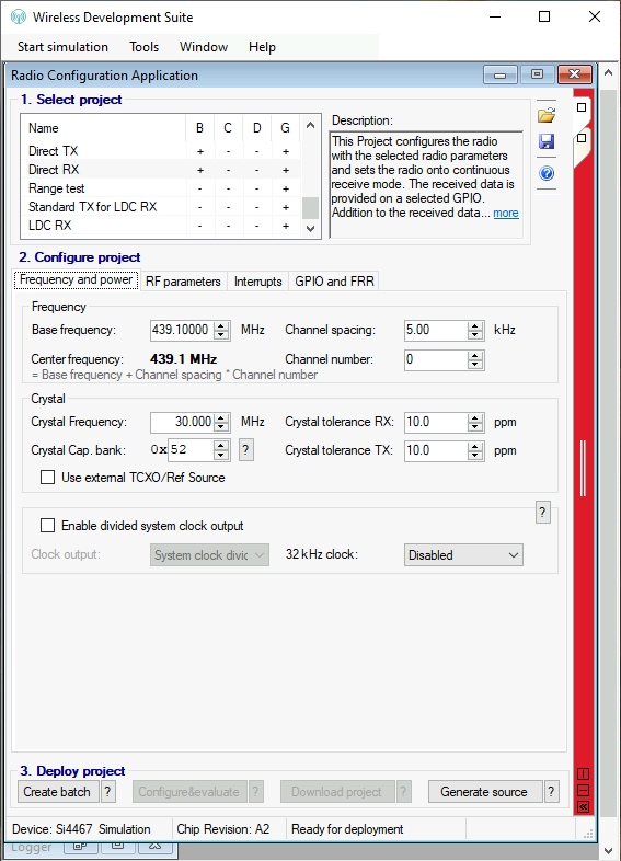
With this utility, you can set parameters for the chip and generate source code for a generic C programming environment. This proved invaluable, though it took awhile to get the hang of how the output code was structured. It’s really intended for the official development board from SiLabs, but turned out to be pretty straightforward to translate to my board.
Generating a Signal
Using WDS, I configured the chip for its CW test mode. This is actually likely one of the most frequent configurations I’ll use, since one of my use cases here is to underutilize this fancy chip to make it just a $3 UHF LO :-). I opted for a 5th order LPF at the output, in addition to some harmonic attenuation that happens in the class-E resonant tank. So I had hoped the output would look clean, but you can’t know until you test it!
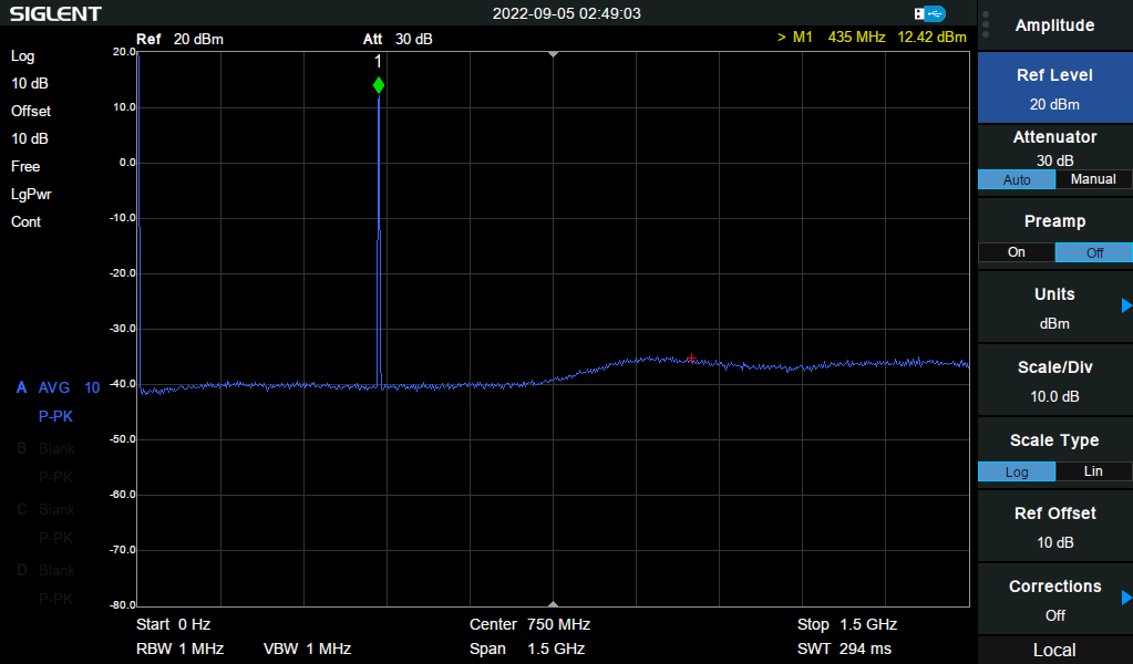
Very clean indeed! I also realized at this point that if I want to venture into UHF, I will some day want to upgrade to a spectrum analyzer with more bandwidth. Can’t see past the 3rd harmonic on mine, ack!
I was also quite satisfied to see that the output power tends to be about 12.5Bm. I’m getting 18mW of output power, so I guess the 0805 components did fine, compared to the 0402s that SiLabs specifies. Whew!
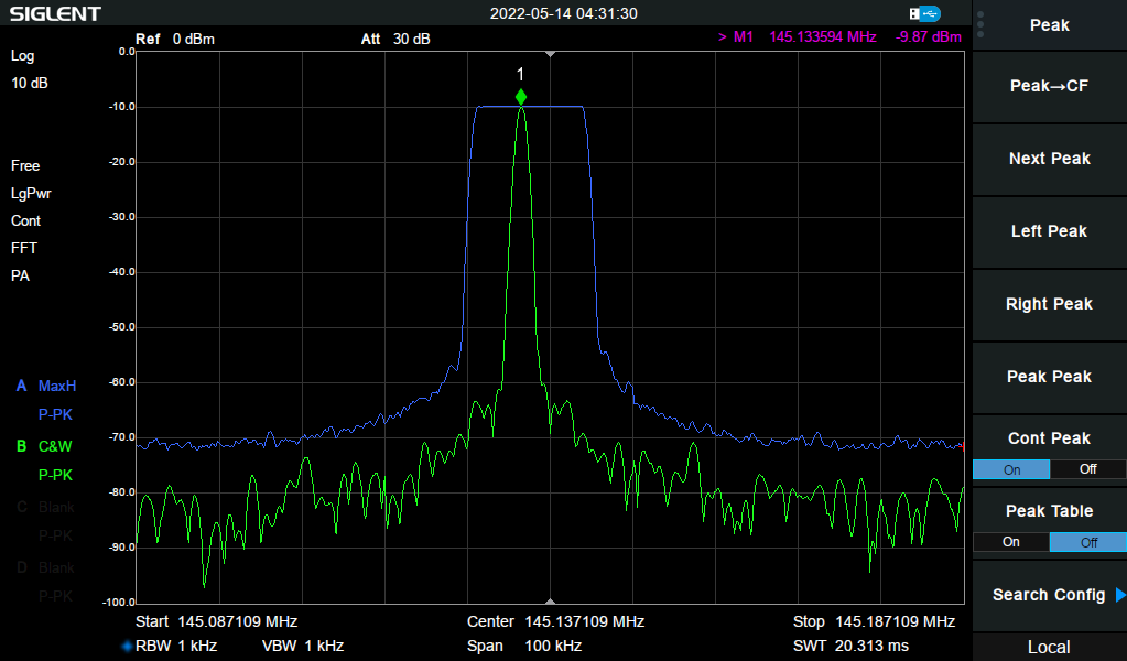
Next, I wondered how stable it is. I narrowed the bandwidth of the analyzer to 5kHz and let it run for about 15 minutes:
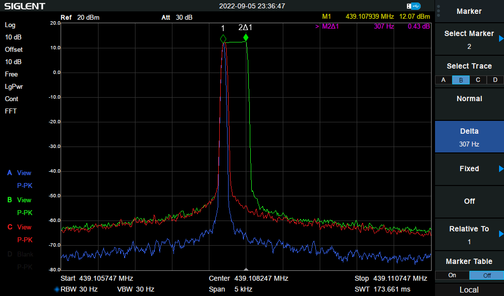
The green trace shows the full 15 minute sweep in max hold. I turned on the red trace in max hold at 12 minutes, so it shows the range of the last three minutes in the test. And the blue trace shows the instantaneous result at the end of the test.
I was very happy with this – it very consistently drifts when transmission is started, but quickly stabilizes on a consistent frequency for the long term. And the fact that this is less than 5kHz total makes this a very good start (compare to my VCO experiment above!).
Real-world testing
I wrote a little firmware sketch for the ATTiny1626 microcontroller that’s onboard to turn it into a little CW beacon. It just transmitted my callsign every 30 seconds or so. This was just with a little stub antenna, nothing fancy. I set the transmitter on a table in my carport, grabbed my FT-818, jumped in the car, and drove around a bit.
Recognizing that my area is semi-rural, with lots of house and Louisiana’s distinctive foliage, I wasn’t sure what I’d find. As I drove around, I made some notes about where I could copy the signal, and where it faded. One very interesting thing was the clear warble of multipath distortion – never heard that before, UHF is fascinating!
Anyway, depending on the obstructions, it wasn’t completely predictable where I’d pick it up. But with only 18mW of output power, I had clear copy as far as 3.2 miles from my home. Amazing! Within about half a mile, I could hear it everywhere, with no empty zones where it might disappear.
That means this power level will be more than adequate for a lot of little sensor telemetry projects I plan to do.
Conclusions
I think I’ll end this post here, with a successful implementation of the Si4467 as a CW UHF source. I’ll make some more posts about digging into the other features of the chip. Here are my initial concluding thoughts:
- I am really excited to work out a $3 UHF source. That it can also do a lot of fancy tricks (like 2FSK, etc.) is icing on the cake. Quite happy with it!
- The drift could still be better, so I think revision 2 will include a TCXO and we’ll see if that dials it in a little better.
- This chip is quite sufficient to drive a mixer as the LO in a UHF homebrew project.
- Even at 18mW, there’s enough power to get a kilometer or so of reliable reception, though I’ll explore that a little more in the next posts.