Experimenting with 2SCR573
I’m always hoping to find modern, in-production parts that can be used as RF power devices. Proper RF power transistors are crazy expensive, but it does seem like some parts (like the popular IRF510) can be made to work for RF purposes, despite not being properly intended for it. This post is about trying out the 2SCR573 – a general purpose BJT power transistor that weighs in at about $0.70 apiece. If it works out, it could be a neat option for linear QRP power amplifiers…
Introduction
I was lamenting in an online forum that it’s tough to find good transistors. All the cool kids of the past used a lot of parts that aren’t really made anymore. Or, in some cases, you can sort of find them, but maybe from sketchy places where there as likely to be counterfeits as anything else.
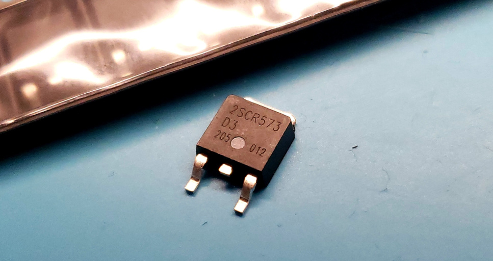
Someone suggested that I check out the 2SCR573. It’s a TO252 packaged BJT that the datasheet says is for “power driver” applications. It’s even got a complementary PNP part, the 2SAR573, which whets the appetite for some other interesting possibilities too. The package can handle 15W of dissipation, and it’s rated for 50V supply, 3A collector current, and GBWP of 320MHz. Delectable!
I ordered 10 of them as a tack-on for one of my many orders from Mouser. They went into a folder for safe keeping, and I forgot about them. This week, though, I remembered them, and pulled them out.
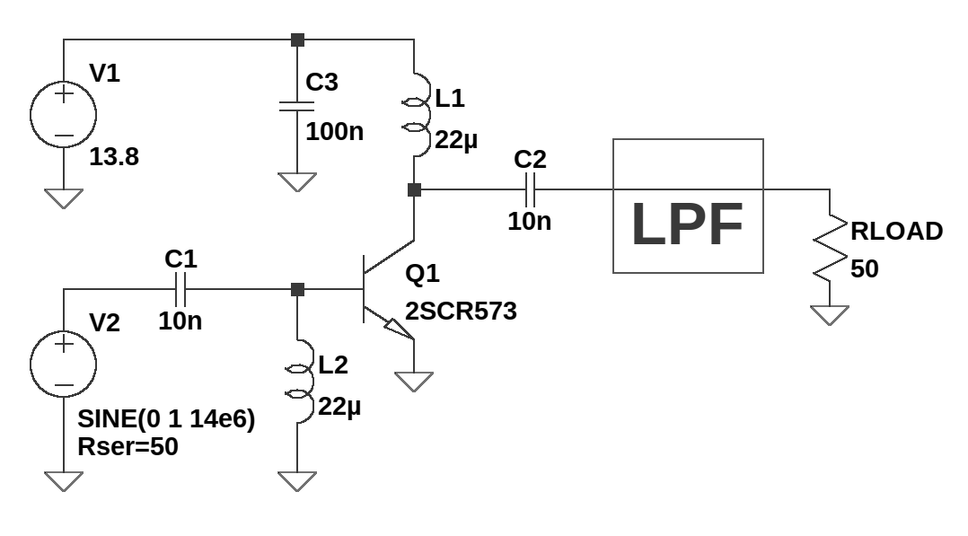
Having learned from some failures in the past, I didn’t really want to build a big, complicated amplifier out of these before I know that they will actually amplify at HF. None of the specs in the datasheet seemed to be of concern, but starting small seemed like the best choice. So, I whipped up a little schematic for a simple class-C HF amplifier with parts I have on hand. There would be some better choices if I cared a lot, but this is just a quick sketch to validate the part:
Construction
I haven’t done any for awhile, but I thought I’d just whip it up with ugly style construction. It’s got a whopping eight parts! I soldered two SMA connectors on a scrap of copper clad board, and hot-glued on the transistor, upside down in dead bug style. The rest of the parts are flying leads, ultimately coming out something like this:
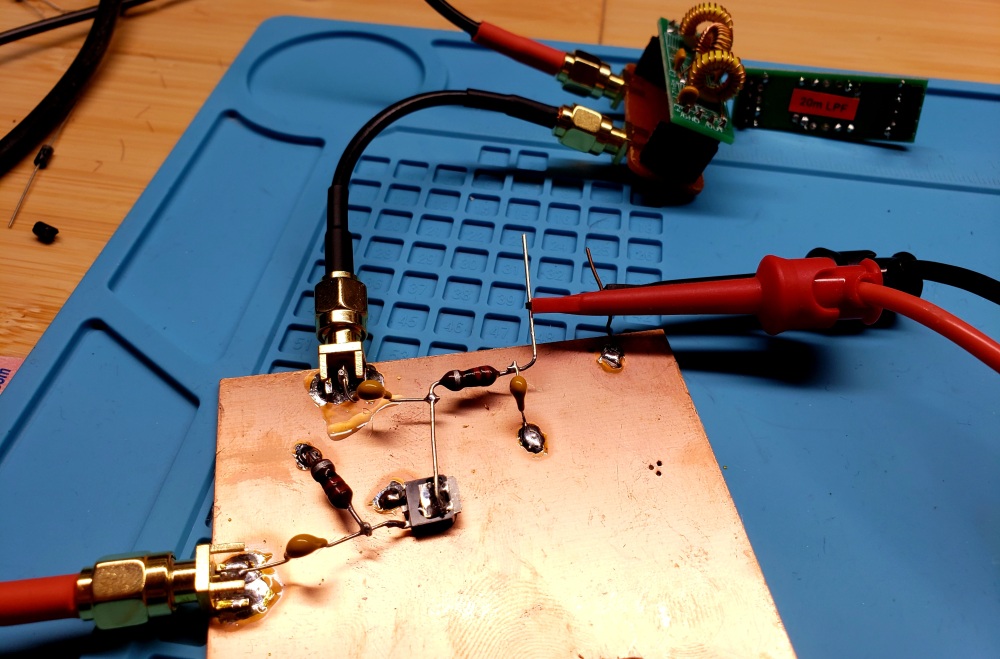
Ugly, but it works. And it’s got a heck of a ground plane ;-). I gingerly powered it on, and the over-current protection instantly kicked in on my power supply. Glad I set that rather conservatively… after a bit of staring blankly at it, I realized I had bent a flying lead too close to the copper, and was shorting the supply directly to ground. Ah, the joy and tragedy of ugly construction.
After fixing that, it powered on just fine – zero current, as expected, being biased for class-C operation. It will need a signal to come to life.
Initial testing
I fed it some power, dumping its output into a dummy load across one of my oscilloscope inputs. Bringing up the level slowly, everything seemed to be working OK. I was able to get almost 2W out of it with a 12V supply.
Feeling a bit too brazen, I ramped up the supply voltage, eventually reaching 20V. For a brief moment, I had 8.2W of output power on 40m. Wow! And then it blew the transistor. So, I guess I found the danger zone. It was the gate-emitter junction that fried, becoming a short. That’s OK, I had nine more, and I don’t ever intend to run it that hot.
EMRFD has a little section on pages 2.34-2.35 about class C transistor waveforms. With a strong inductive supply, it seems the collector voltage can get a lot higher than expected. I suppose the normal 2x of the DC supply voltage is only for linear amplifiers. Since this is operating non-linearly into an inductive supply, voltages can get crazy. For 8.2W output, that’s a peak-to-peak voltage of 57V! That’s definitely more than the 50V rating for the transistor.
Anyway, I installed another one, and got a bit more rigorous about my testing. With a sensible 12V supply, it didn’t really get hot. Even at 13.8V, I ran it at about 3.8W of output power for 60 seconds, and it still passed the finger test. That was quite encouraging!
Here are some useful results, all with a 12V supply:
| Freq | Pin | Pout | Gain | Supply Current | Efficiency |
|---|---|---|---|---|---|
| 7.040 MHz | 21 mW | 1.63 W | 18.9 dB | 184 mA | 73.7% |
| 7.040 MHz | 66 mW | 2.7 W | 16.2 dB | 313 mA | 71.8% |
| 14.040 MHz | 20 mW | 0.439 W | 13.3 dB | 80 mA | 44% |
| 14.040 MHz | 63 mW | 1.9 W | 14.9 dB | 220 mA | 73% |
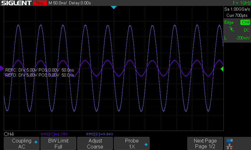
For those graphically inclined, here are some oscilloscope waveforms. The small signal is the signal generator directly into the dummy load, and the large signal is after putting the amplifier in the middle. The load is a decent 50-ohm dummy load I blogged about in another post.
40m, 2.7W output:
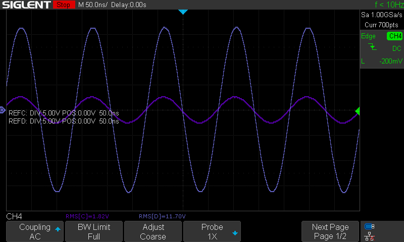
20m, 1.9W output:
Conclusions
This was a pretty encouraging test. After doing some simulations in LTSpice, it seems like this 2SCR573 behaves roughly like a 2N2222 or 2N3904, so designing circuits around those models should get a circuit in the ballpark. This TO252 package can soak a ton of heat, so proper PCB design should make it quite usable.
My guess is I can make it work at decent QRP levels as a single-transistor class-C amplifier, e.g. for a digimode or CW transmitter. More, I think in a push-pull pair, I might be able to shoot for the 5-10W class as a linear amplifier.
This is a rather delightful find, as there isn’t much between the typical small-signal jobs that are so common, like banks of BS170s, and the IRF510. And compared to the latter, this transistor doesn’t have quite the same total power envelope, but it should be much easier to drive with lower input levels.
And for $0.70 or so in modest bulk, it’s really cheap. Cheaper than an IRF510, anyway! Next step will be to build a proper amplifier, with some load matching, attention to input impedance, and some feedback networks to see what kind of flat gain bandwidth can be achieved.