Testing LT1818 for RF Use
I don’t see a lot of people using high-speed opamps in RF circuits, but I wonder what they are useful for. After sketching out a few ideas, I thought I’d pick up the LT1818 from Analog Devices. It’s a pretty snazzy one… putting it on a little test board and putting it through some paces suggests it’s quite usable for HF and low VHF, at the very least!
Introduction
Several articles I found seemed quite insistent that it was once the case that opamps were not really relevant above 5MHz. But with current generations of available chips, this is certainly not the case! The LT1818 has some really impressive specs. It’s got a 400MHz gain bandwidth product, and 2500V/uS slew rate. Applying some back-of-napkin engineering, with FMAX = SR / (2*PI*F*Av*Ag), it looks like it should be useable well into VHF.
Today’s experiment set out to test this. I’ve certainly been guilty of reading datasheets with a little bit too much naive hope, only to build out a project and be disheartened when reality sets in. I started with a basic inverting amplifier configuration set up for a gain of 10. Note that this is not exactly what I really started with… it’s the finished working configuration. I’ll get to what I learned shortly :-).
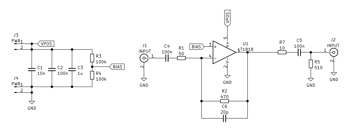
I chose the very small resistors for the input and feedback loop for two reasons. One, I thought I’d play with it as if it has a 50-ohm input impedance. This is perhaps how I would really want to use it in an IF strip or as a voltage gain stage in a modulator, or something. But more importantly, I noticed that all of the example applications in the datasheet use small resistors like this. The internal function of this opamp is a little different from normal ones I’m used to, so I played it a bit safe with similar values to what I saw in the datasheet!
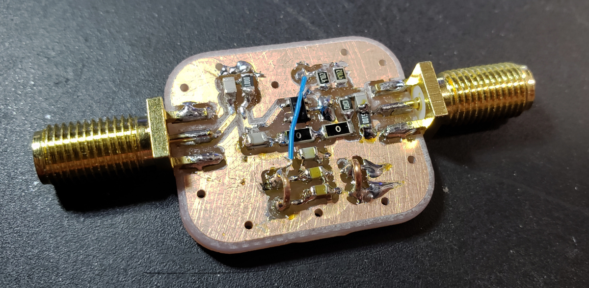
Construction
The board is a tiny little thing – I wanted to make it on a double-sided board so it would have a full ground plane, just in case. I know when device gain gets up into the UHF zone that self-oscillation becomes a real concern, and I didn’t want to take any chances. As such, I economized on space, and came up with this:
At first, I did not have R5 in place, and R7 was a 100R value. I wanted to be careful about how much current I might draw from it. This proved to be overly cautious. First, if the LT1818 is completely unloaded, the gain curve is really weird. It has high gain through about the 17m band, and starts to tail off dramatically. It definitely doesn’t look like it would be useful at higher frequencies, and this threw me off at first!
I do not yet know why it cares so much about being loaded (I suppose it’s something to do with needing some output current for the internal current amplification stages to work right, but that’s just a guess from the datasheet’s enigmatic comments). But when I added a 50-ohm load, the gain curve looked nice and flat. It was clearly more than happy through 30MHz, which is as high as my nice signal generator goes.
But, there was a problem – gain was flat, but it wasn’t what I expected from the ratio in the feedback loop. After staring at the figures in the datasheet for awhile, and wondering if there was just some parameter I hadn’t looked at or didn’t know how to interpret, it hit me. I had a 100-ohm resistor at the output, and was putting a 50-ohm load across that. It was a 30% voltage divider, and so of course the output waveform should look small (I felt pretty silly when I realized that).
So I reconfigured it as shown in the schematic above – a 10-ohm output resistor across a 510-ohm load. This way, I could observe its behavior with some loading (and thus some output current to stabilize the feedback loop?), as if it was followed by a high impedance input stage. And it was quite beautiful! Let’s look at some of the test results.
Test Results
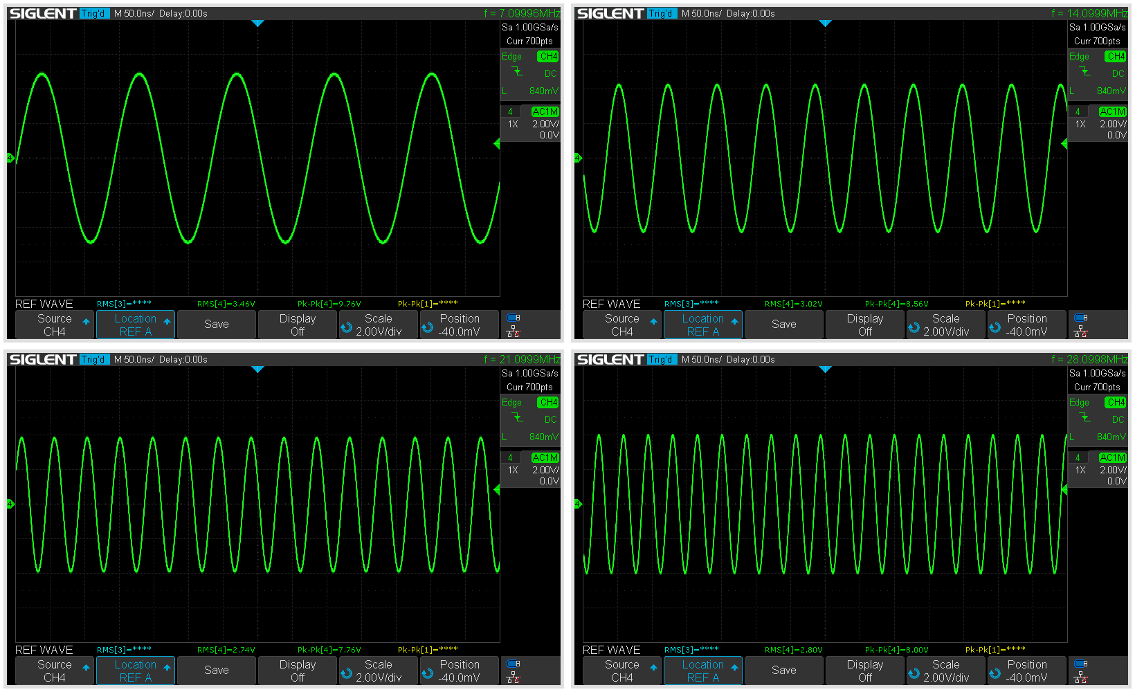
For the first pass, I just attached my signal generator and oscilloscope and generated some HF waveforms. They looked very nice – you can see some variability in gain, but the waveforms are quite clean, and reach nearly to the supply rails. I guess this means the GBWP and slew rate specs are pretty good indicators of successful operation:
The next one we’ll look at is a sweep with the tracking generator. Here is the output from my spectrum analyzer:
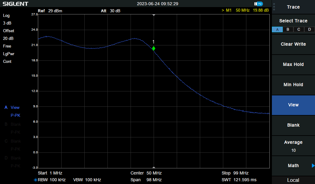
Now, bear in mind that there are two big problems with this result. One, it’s through my directional coupler, which maxes out at 60MHz. That definitely interferes with the measurement going up into mid VHF. Secondly, the 20pF capacitor in the feedback loop (recommended by the datasheet for stability) starts to compete with the 470R feedback resistor as we go up into VHF, and so it will have the effect of killing gain as we go up.
But the salient observation here is that it’s got pretty decent, and quite usable, gain through all of HF and past the 6m band! That’s really encouraging… I could see using this chip as a voltage gain stage in a 6m project, for example. Note that the scale is 3dB/division in the image, so the ripple isn’t quite as bad as it might look, but it is quite a swing. Depending on use cases, it’s probably no big deal, but I might play with it a bit and see if it can be flattened out in the future.
The next measurement is output swing on the 6m band. I can’t do this with the tracking generator, because it only goes to 0dBm. But I found I could use an Si5351-based oscillator with a 3dB attenuator to get to full supply range at 6m. This comes out to about 11.5Vpp – if followed by a low impedace current gain stage, it means we could be pushing a few hundred milliwatts (or maybe more with impedance matching):
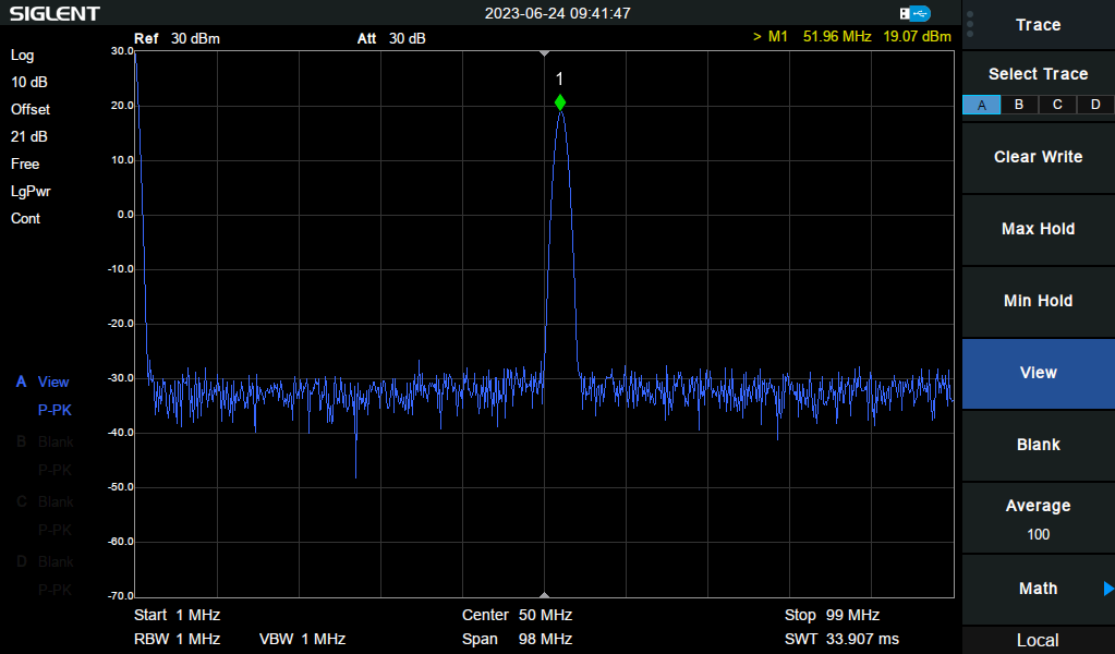
The main observation here is unfortunately not visible on this screnshot, which is that the waveform is replicated quite accurately. The amplifier’s linearity all the way up to this degree of excursion, with 10x gain, and at 6m is excellent. Very satisfying!
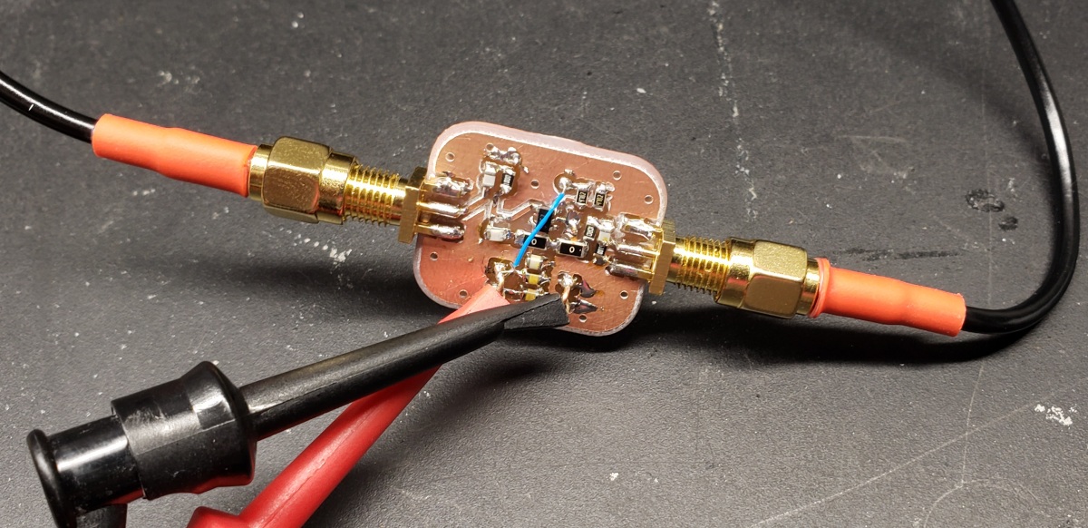
Speaking of linearity, I thought I’d do a two-tone test at the 10m band. This is using my Siglent signal generator, with two channels going into an attenuating combiner, then the amplifier.
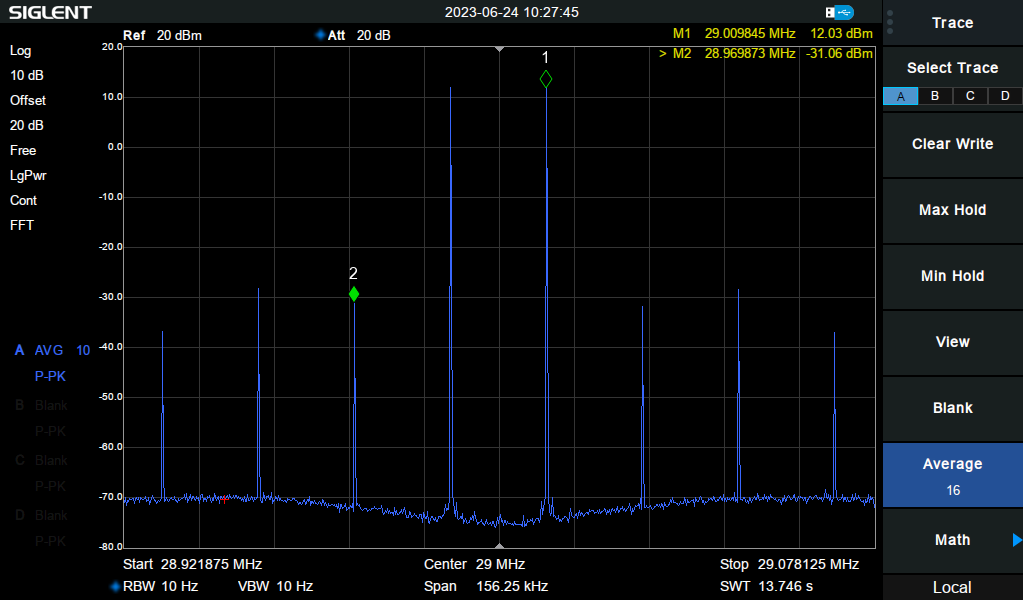
Remember that this is across the 510R load into an open circuit on my oscilloscope, observing it through the directional coupler on my spectrum analyzer. As such, the dBm measurements are not accurate – but you can convert them to voltages as if they were across the analyzer’s 50-ohm load, and get a mental picture of what they looked like. The point is, IMD seemed pretty well-behaved, though it could be better. Given the amplitudes of these signals, though, it seems decent (without any better intuition how conversions from low- to high-impedance stages should look vis a vis intermodulation…).
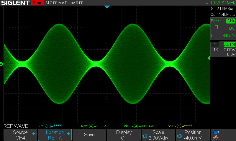
For another perspective, this is what the two-tone test looks like on the oscilloscope. Past about 11.5Vpp we hit the supply rails, and start to get some clipping. Running it at 11Vpp like shown leaves some decent headroom, and it’s a beautiful waveform:
Conclusions
I’ve wanted to play with one of these high-speed opamps for awhile. They clearly behave a little differently, and I find the descriptions of their internal operation tantalizing. I wish I understood more about how they worked underneath. But it seems like they could be practically useful in HF and low VHF applications, and it means some of the convenience of opamp arrangements could be available in IF strips and generating signals for transmit, etc.
I think my next project with this will be to use it as a voltage gain buffer stage into an NPN/PNP transistor pair as a class AB current gain stage. This should allow me to use a feedback loop to control gain and tame thermal runaway, assuming the transistors I ordered are good enough at the target frequencies. If nothing else, it’ll look very different from most ham projects… which is often a good enough goal in itself :-).