Gate driven Hellschreiber beacon
Today I did some more experimenting with the gate-driver based amplifier I built this week, and whipped up a fairly performant little transmitter today. This post describes the layout, some new performance data on the amplifier, and an explanation of Hellschreiber transmission. I tested it as a “beacon” of sorts (really just a PoC!).
Hardware Architecture
Previously, I have tested this amplifier using my benchtop supply to power the gate driver and the IRF510 output transistor, while using my QRP Labs Progrock kit as the signal source. This wasn’t really how I intended the board to work, so today I went to the extra trouble of arranging things somewhat better.
First, I swapped out the Progrock for my Adafruit Si5351 breakout. This has a couple nice advantages: (1) I have more control over the Si5351 configuration, (2) it’s simpler, and (3) it mounts to the amplifier directly, so there’s less cabling. Next, I added a Teensy 3.2 microcontroller board. And when I realized that the Adafruit breakout can be powered at 3.3v, I just decided to power the low voltage side of the amplifier board directly from the Teensy.
On the benchtop, it looks like this:

On the high voltage side, I set up my benchtop supply to power the MCP14A0601 gate driver, and dragged in a 12v battery to power the IRF510. Note that I had been unable to power it higher than about 11v because of some instability issues. With this different configuration, I can experiment with different supply levels for the gate driver and the output transistor.
So everything looks like this:
![]()
In this configuration (8v supply to the gate driver seemed to be optimal with some experimentation), I found that I was getting substantially more power out than in my earlier experiments. Pushing more power to the IRF510 allows delivering more power to the load, but that same voltage to the gate driver reduces output power. Today’s sweet spot yielded over 18 Vrms into a load, making for over 6W.

This architecture also allows me to key the amplifier’s output by running the ENABLE pin from the MCP14A0601 to an output pin on the Teensy 3.2. This is “hard keying”, which will have substantial clicking and splatter. Today I did all of my testing into my dummy load.
A future project will capitalize on my various lessons learned playing with this prototype, and add a keying circuit to soften the keying waveform and make it friendlier (though with Hellschreiber, the baud rate is high enough that it’s going to be somewhat harsh no matter what!).
Hellschreiber Modulation
With this setup, I actually have a full “transmitter”, so I thought I would rig up a little test. Since Hellschreiber is my favorite digital mode, it seemed like a good choice for today’s playtime.
Hellschreiber, in its original implementation, is a continuous wave OOK mode. You can read about how it works at N4SSP’s web site.
It’s a very simple facsimile mode, transmitting pixels at a certain rate – when the key is down it’s a black pixel, and when the key is up it’s a white pixel. Conventionally, a column has 14 pixels in it, and the pixel clock is 122.5 baud. This makes about 2.5 characters per second, or 25 words per minute.
For my test, I wrote up an Arduino sketch that embeds a hard-coded array of characters as a message to send over and over. It’s a Hellschreiber beacon, more or less. Even though I’m transmitting into a dummy load, I figured I’d make the message my callsign: “N5HXR”.
Rather than a full 14-pixel font, I thought I’d just double my pixel time and make it a 5x7 pixel font. Here’s what the data looks like in the sketch:
byte alpha[6][7][7] = {
  { {0, 0, 0, 0, 0},
    {0, 1, 0, 0, 1},
    {0, 1, 1, 0, 1},
    {0, 1, 0, 1, 1},
    {0, 1, 0, 0, 1},
    {0, 1, 0, 0, 1},
    {0, 0, 0, 0, 0} },

. . .
If you look closely, you should see that the 1s and 0s encode pixels, and there is a capital letter “N”. This array has 6 entries, making the message “N5HXR “, which will be transmitted over and over again.
This little transmitter is very simple; we initialize the Si5351, configure our output frequency, and enter an infinite loop sending pixels periodically. You can read the code here, with the message characters in this include file.
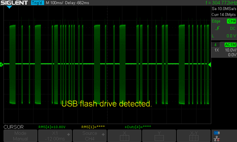
The output looks like this (note the hard keying that needs some shaping!). This shows all five characters, for fun see if you can identify the columns and work out the font shape!
Testing the transmitter
As I described, I had the transmitter running into a dummy load, at 7.0885 MHz (in the Feld Hell Club’s preferred frequencies for Hellschreiber use). I set up my FT-891 portable rig, tuned to the same frequency. I have a Raspberry Pi 4 connected for digital modes, and set it up to decode the beacon using FLDigi. It came through loud and clear (being in the same room, of course!):

Next Steps
I want to proceed with my former plan to make a push-pull version of this amplifier. I think this particular gate driver is really only practical up to the 40m band, but a single-band transmitter is a reasonable goal this early in my homebrew “career”.
I’ll need to study up on some keying circuits, and work out how I want to set up the power supply for this next stage in the project. I’ll need to power a microcontroller, the gate driver at a good supply level, and then have full power available to the IRF510.
Finally, my hellschreiber experiment is quite successful. I’m happy to see FLDigi decode it just fine – I need to flesh it out with a full 5x7 pixel font, and work out the logic for queueing characters for transmission so I can approach something usable in the next iteration.
As always, building things and seeing them work is very fun!