Push-Pull Gate Driver Amplifier
Building on the gate-driver based power amplifier, I have built a more powerful version that uses two gate drivers into a 180-degree combiner. This push pull arrangement yields increased power, but also raises interesting new questions that I hope to answer as I learn more.
![]()
Extending the Idea
Previously, I wondered if running two MCP14A0601/2 gate drivers into two IRF510 mosfets might yield more power at similar efficiencies to what I saw with only one. Furthermore, there were some observations from testing that simpler amplifier that I wanted to add to the system, as I get closer to a full-suite transceiver design.
While testing different supply voltages for the power amplifier, I found that I could increase the power substantially beyond the 4-5 watts that I could reliably get from a single IRF510 and gate driver. But this isn’t so practical, since I hope to operate my eventual transceiver project off of portable batteries. Using 12V, I can increase power by increasing the load on the output transistors, but there are some real limits eventually.
I had previously built a class B amplifier yielding roughly one watt of output power… I wondered if I could do the same thing with two gate drivers and two IRF510s. And using the MCP14A0601/2 gate driver, there are two variants of the gate driver: inverting and non-inverting. It sure seemed like these devices should lend themselves to a pretty simple arrangement, so I gave it a shot.
Other Goals
This next design is also motivated by several other objectives. First, my Dad had asked if I was ever going to make something that wasn’t a bunch of boards all connected with a mess of wires. Since I feel like I’m getting close to something good enough to go to press on my final transceiver project, I thought this might be a good time to integrate the microcontroller, RF synthesizer, and power supply in a single-board power amplifier / transmitter solution.
Secondly, I have been using a “hard keying” approach for activating the transmitter. For real use on the HF bands, I do want to be a good RF citizen, and apply a key shape to my key-up and key-down events. This should reduce unnecessary pollution of the bands by narrowing the keying side-bands that inevitably occur when turning a transmitter on and off. So I wanted to experiment with adding a keying circuit too.
The Schematic
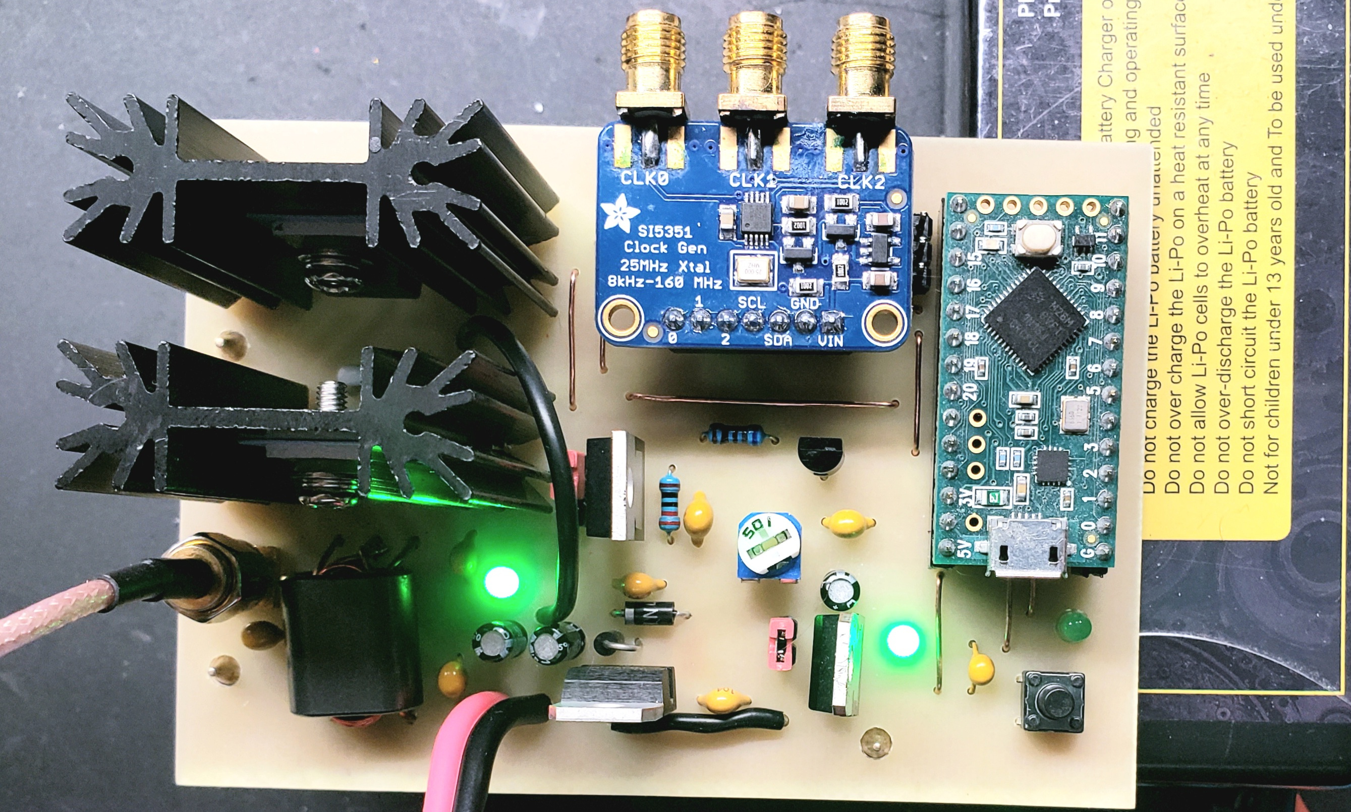
The result is the largest PCB I’ve milled so far, with a lot of things going on. The whole thing is as shown in the image below:

There’s a little more than is strictly necessary in here, so I’ll hit some of the highlights. The power supply components provide a few options. The main circuit supply should be at least 9V, and is regulated down to what I labeled “8V” in the schematic. But this is adjustable using R9 to create a supply anywhere from about 5V to 10V. This lets me experiment with different levels of supply voltage for the gate drivers.
The LM7805 (U2) regulates a 5V supply, that can be used to power the Teensy LC microcontroller board (it has its own local LDO for dropping that to 3.3V for its own purposes). The jumper at J1 allows me to separate the 5V line from the main board supply. This is so I can power and interact with the microcontroller while separately powering the power amplifier with an external supply without risking some interaction between the 5V regulator and my computer’s USB power supply.
Q2 and its associated components make up the keying circuit. I’ve done other experiments shaping the supply to the output transistors, but this time I wanted to see how things would go if I did the shaping at the gate driver stage (in retrospect, I don’t think this was the best choice). In case that didn’t work out, though, I added jumper J2, which lets me choose between the shaped keying waveform and just attaching the gate driver supplies to the adjustable regulator at U4.
As in previous amplifiers, I left any output filtering off the board so I have more flexibility if I want to experiment with other bands. In all of my testing, I have run this amplifier through a 7th order low pass filter to suppress harmonics and keep things legal.
Since I’m starting to play with user interface and firmware, I also added an extra indicator light at D6, an input button tactile switch at SW1, and I wanted to make sure that I could bring out some other microcontroller pins at J5 to add more I/O. I envisioned perhaps adding an iambic keyer or something, and wouldn’t want to just bodge in some stray wires if I didn’t have to. No sense limiting my options!
Construction
This is my largest milled PCB that I’ve made so far. I used up so much board space that I decided not to do any edge routing, and just use a full 70x100mm PCB blank. This made for some harrowing moments, trying to keep traces and holes away from the clamps that hold the board in the mill. I really didn’t want to start cutting into a 1/4-20 bolt head by accident! But with some apprehension, I charged forward and milled the thing. It came out quite nicely:
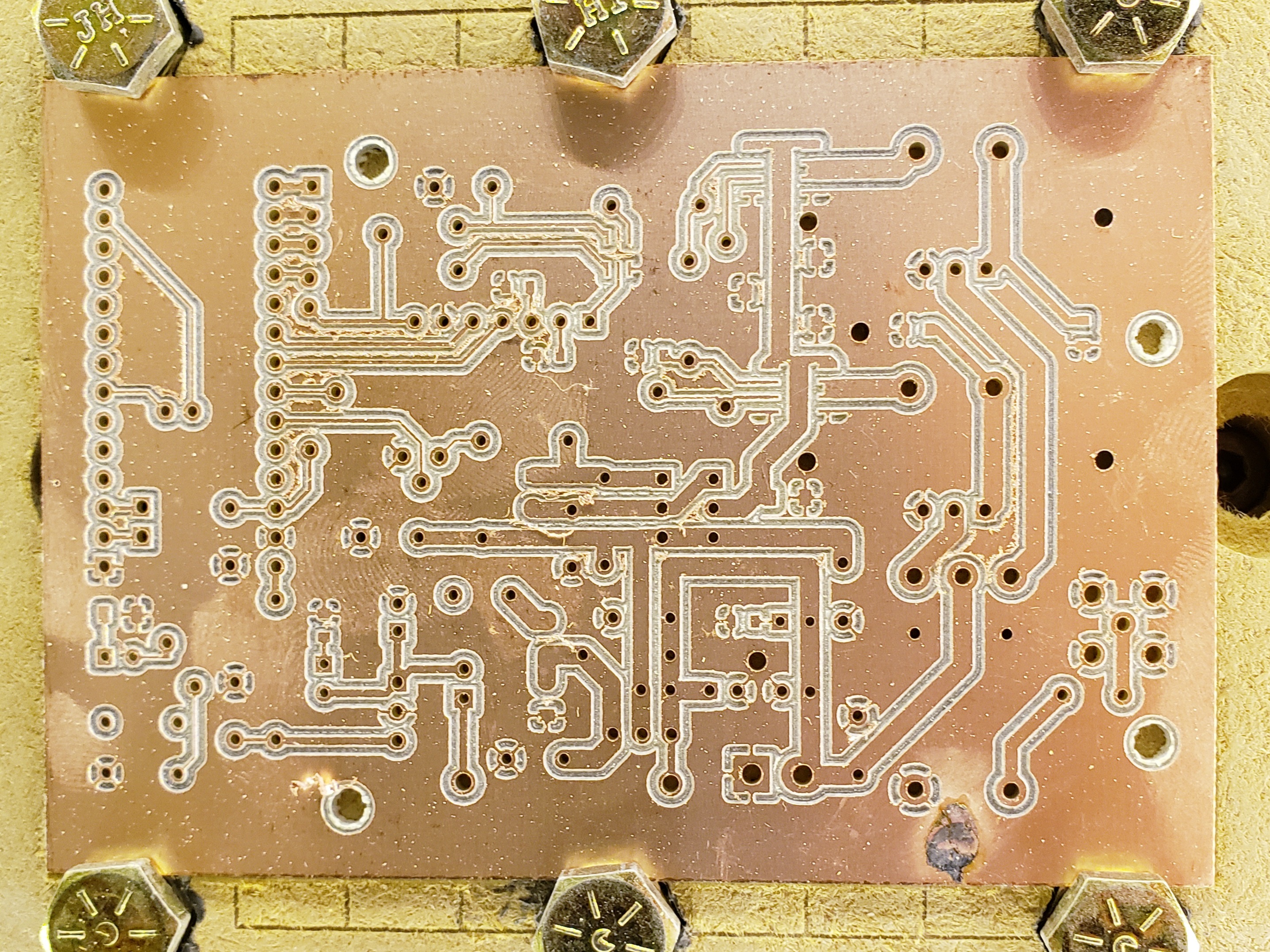
Since my last board, I’ve acquired a very large assortment of SMD parts. This board uses a bunch of them, and it makes for a pretty clean top side. The bottom, though, has quite a bit going on: two gate drivers and a bunch of caps and resistors:
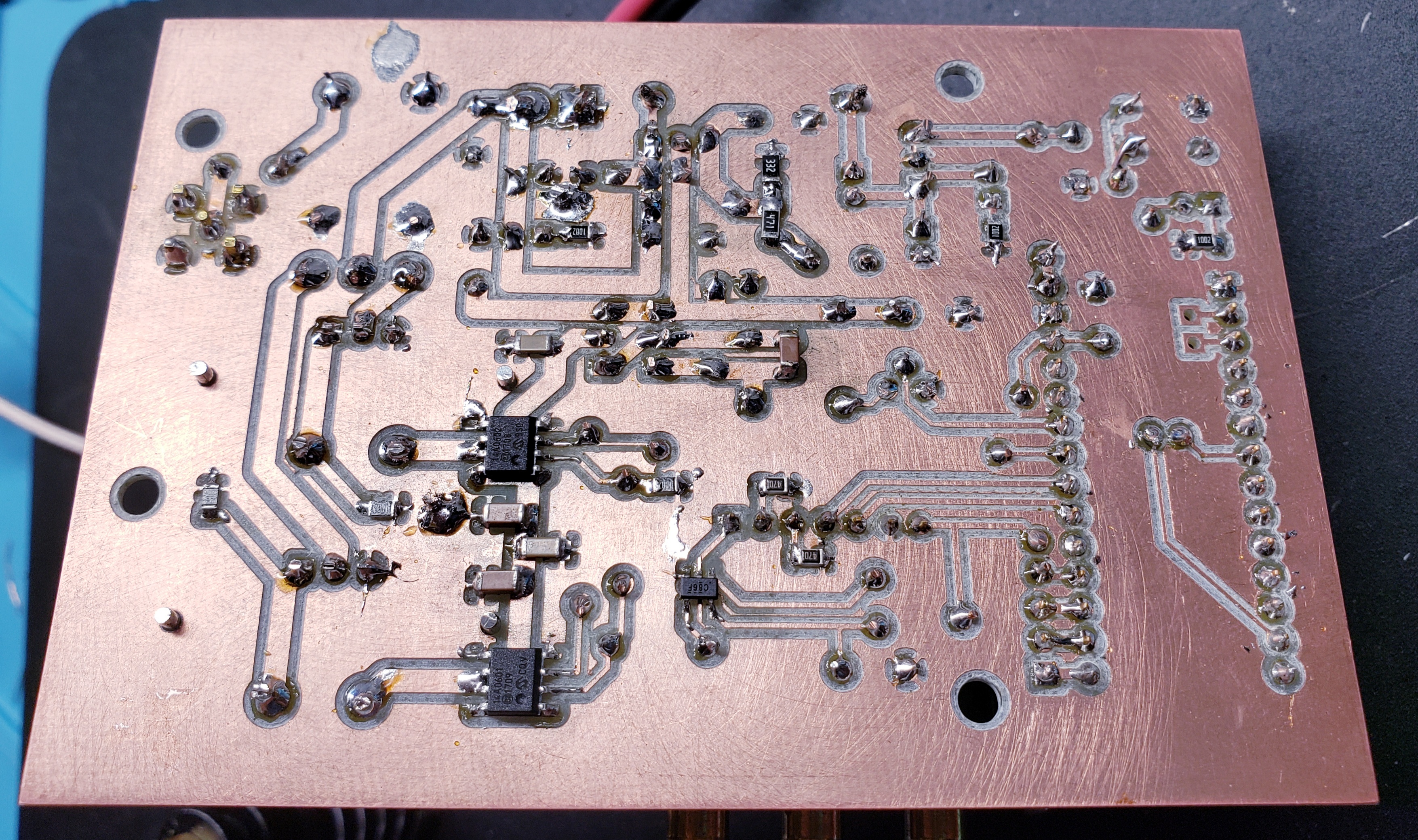
The gate drivers are SOIC-8s, while the other SMD parts are 0805- and 1206-size components. I don’t mind working with these sizes at all. In previous projects, I’ve gone down to 0603, which is getting a bit too small for comfort. But anyway, with this board’s results, I’m quite comfortable with milling SMD stuff at this point, so I expect my future projects will be more and more SMD.
Initial Testing, Learning, Repairing
When I first fired it up, I was excited to see something like 9 watts appear! But things deteriorated rapidly, and strangely indeed. The power shot up pretty fast, and tweaking settings didn’t make sense of things. I was worried that there might be some interference between the gate drivers, or I had something wrong.
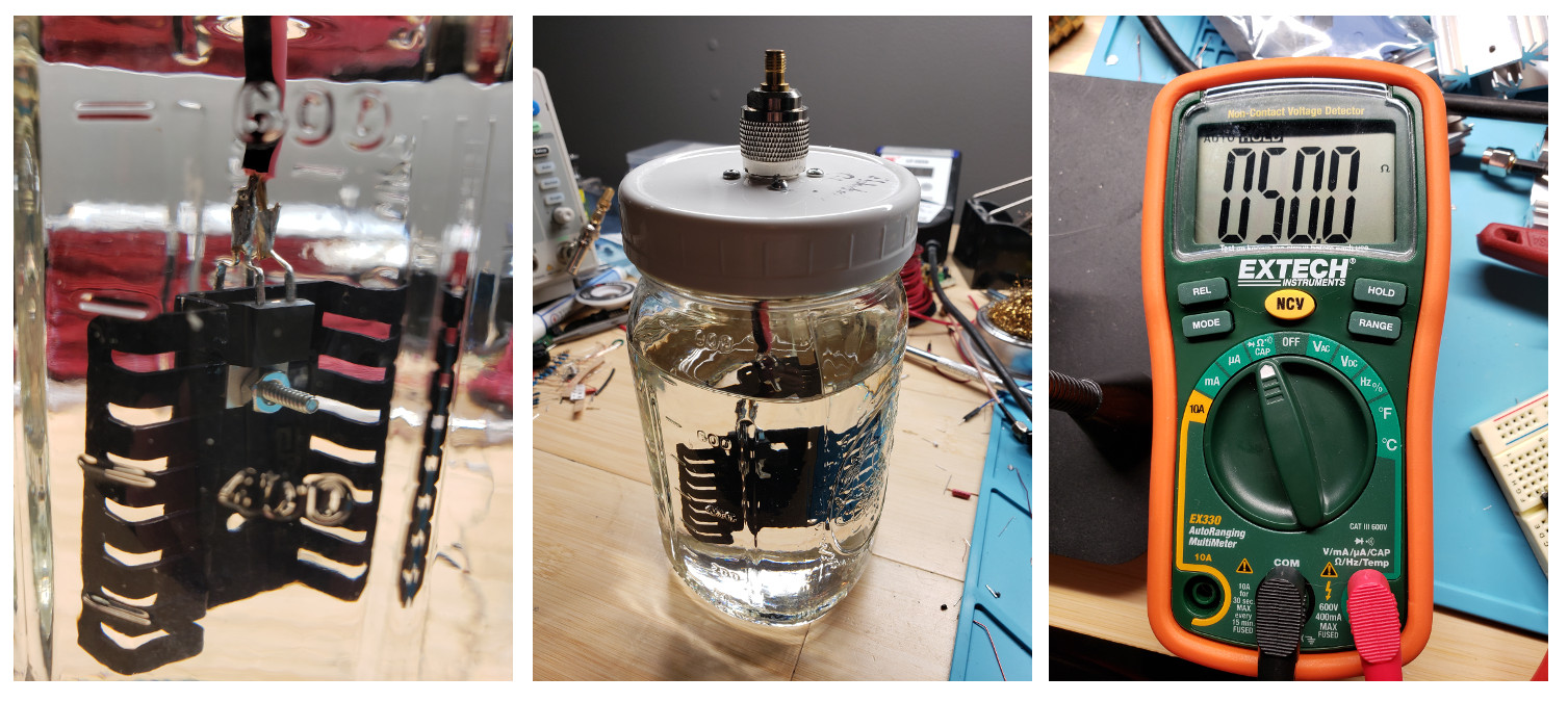
VK4HAT on the QRZ forums suggested my dummy load might be failing. So I checked, it was REALLY hot to the touch. I powered everything off, and measured my dummy load. While normally being 50 ohms, it was 70 ohms. And as it cooled, its resistance was changing. A few more experiments with the amplifier, and I realized that my dummy load must have exceeded its rating (perhaps awhile ago, during testing of the previous amplifier), and it was in the throes of a violent death. Alas.
I grabbed a couple 100 ohm, 35W, TO-220 resistors and a heatsink, and submerged them in mineral oil. For about $6, I hope this will work for awhile. Sweeping it with the NanoVNA showed it’s less than 1.1:1 throughout the HF bands.
But this was just a setup for round two of disappointment – when I hooked everything back up, power was down to about 3.8W, and the current draw was… substantial, to say the least. I scoped a few of the traces, and found that one of the IRF510s and its gate driver (the inverting one, the MCP14A0601) were fried. The gate driver’s output was locked at high voltage, and the IRF510 had cooked itself.
Oh well, this is why we multiply all quantities by 2 when we order from Digikey. I swapped them out, made a change to my firmware so I wouldn’t accidentally leave the transistor on full blast when ending transmission (oops), and forged ahead.
Testing Functionality
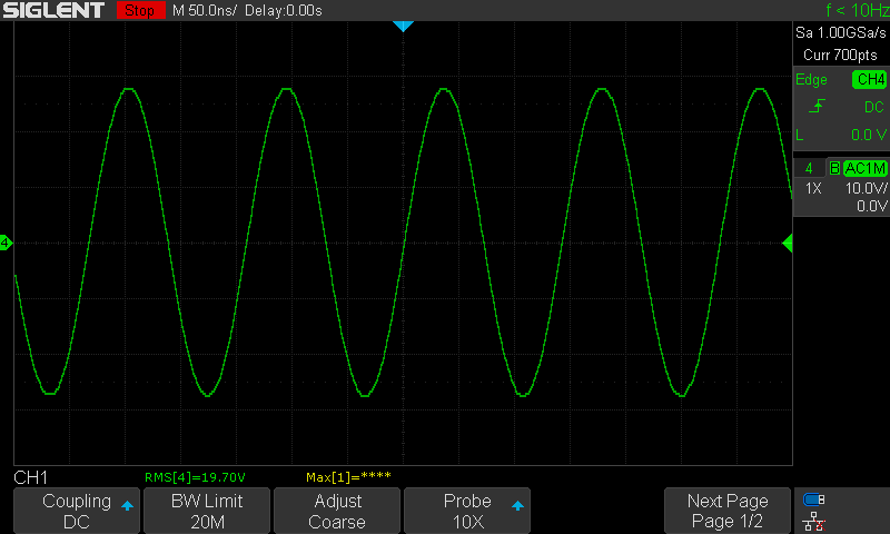
Well, after all the ordeal, I finally sat down to characterize the amplifier. The first test against a (much more) reliable dummy load, with the gate driver supply set to 5.65V (close to the bottom of the range) yielded 9.5 Vrms, for 1.8W of output power. It was stable, the waveform was clean, and I was renewed in confidence that my setup was going to bear fruit. So I raised the gate driver supply in steps until I got to where I expected the optimal point to be – 8.5V. With a 12V supply, this yielded a comfortable 7.8W:
Experimenting with different supply voltage levels, I did not experience any of the instability / oscillation issues I ran into with the previous amplifier. Perhaps this one is inherently more stable for some reason? Anyway, I could naturally increase output power with higher supply voltage (I tested up to 13.8V with 10.04V gate driver supply).
Curious Thermal Behavior
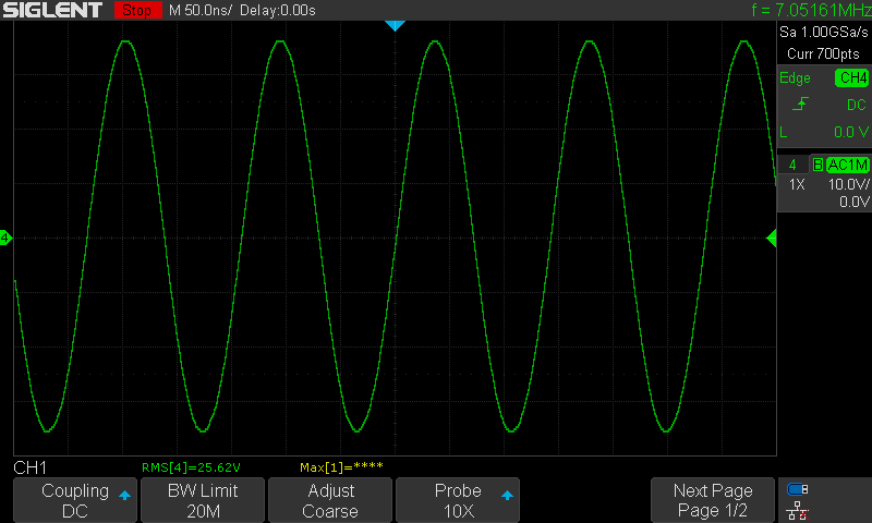
During this testing, I started to notice some thermal behavior that was quite surprising. E.g., set for 12v supply, 8.5v gate driver supply, if I sustained transmission for 5 seconds, the power level would rise to 8.9W. After 10 seconds, 11.42W, and after 19.8 seconds the power level would level off at a stable 13.1W:
When I mentioned the behavior to VK4HAT on the QRZ forums, he suggested some error in construction, such as a cold solder joint that expands to conduct more over time. I did go through and reflow all of my solder joints and test conductivity with a multimeter, but that resulted in no change in my results.
I know that a mosfet shouldn’t exhibit thermal runawawy like a BJT would. KG5ZID suggested saturation or thermal runaway in my output transformer when I asked him on the YSF#33360 radio hackers active night this past Sunday. I don’t know much about that, so it seems like another little corner of physics to research. His intuition was that the reactance of the windings in the transformer may reduce with heat, and thus change the impedance load on the amplifier.
I think I’ll post a question about it on the QRZ forums, and see if the college of wizards can shed some light on it for me!
Spectral Purity Testing
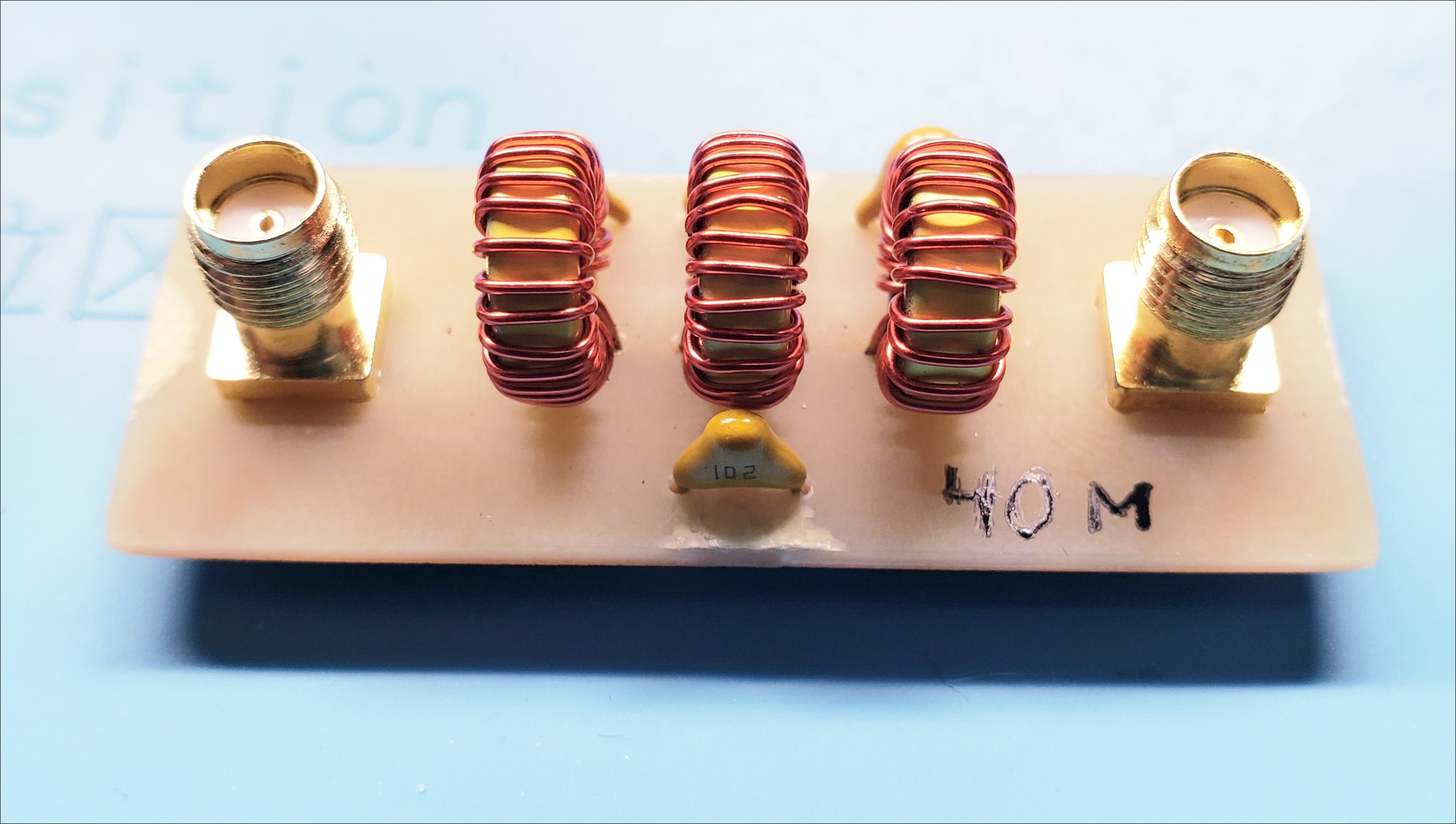
Before doing any testing with an antenna, I needed to check spectral purity. I need to have all unwanted emissions below -43dBc. During all of my testing, I’m inserting a 7th order low pass filter I put together for 40m awhile back:
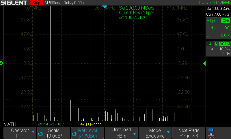
It’s not perfect, but I use the FFT feature on my Siglent 1104 oscilloscope. Results came back very encouraging, with the 3rd harmonic at about -53 dBc!
Ready to do some on-air testing with my new firmware, which has a user interface and everything!
On-Air Hellschreiber Transmit Test
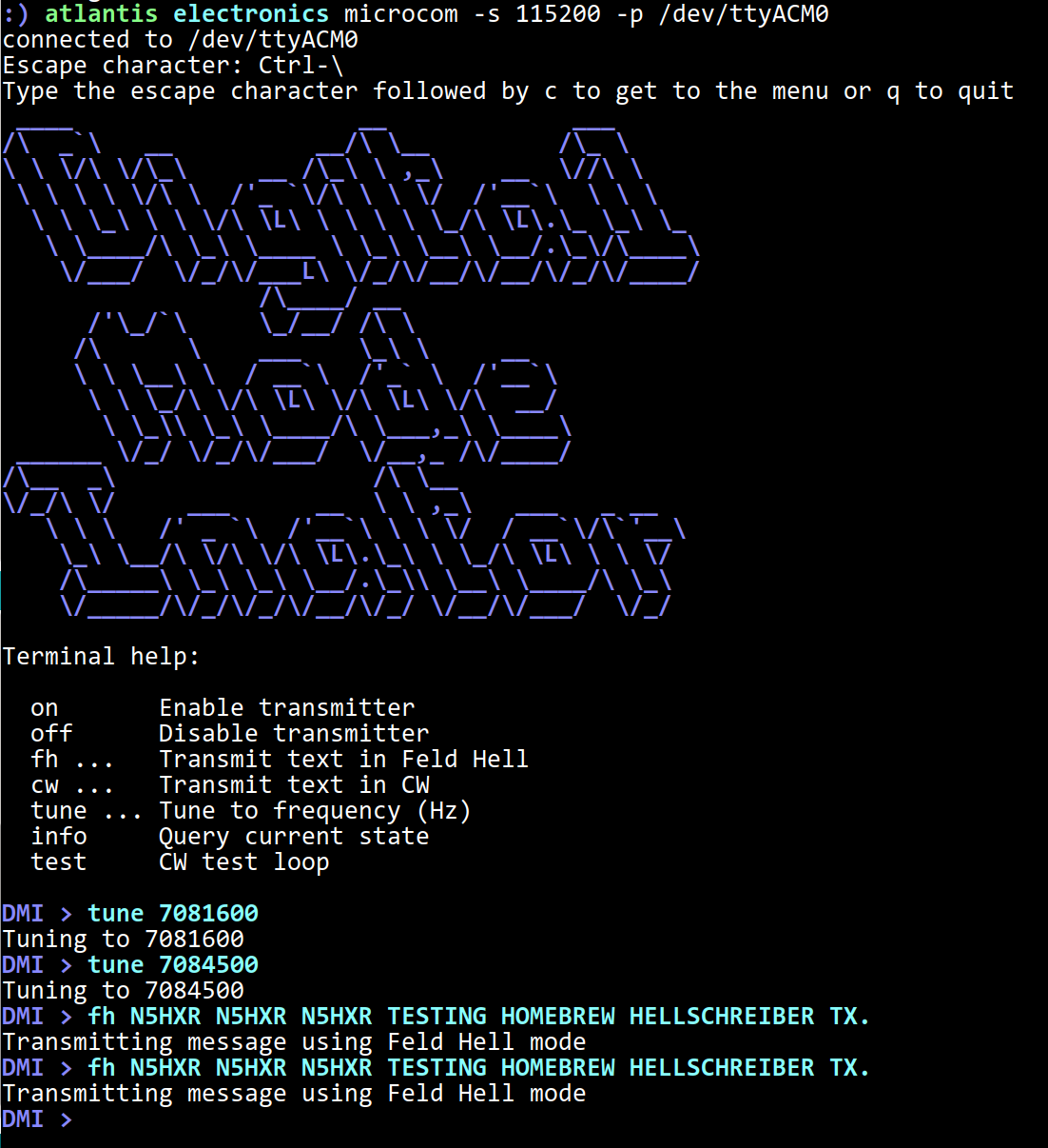
With the microcontroller connected to my computer’s USB port, I can connect to its serial port using microcom. The interface I wrote is a simple TUI, which lets me control the transmitter by submitting commands to an interpreter loop. Here is an example of tuning to 7.0845MHz and transmitting a message using Hellschreiber (Feld Hell):
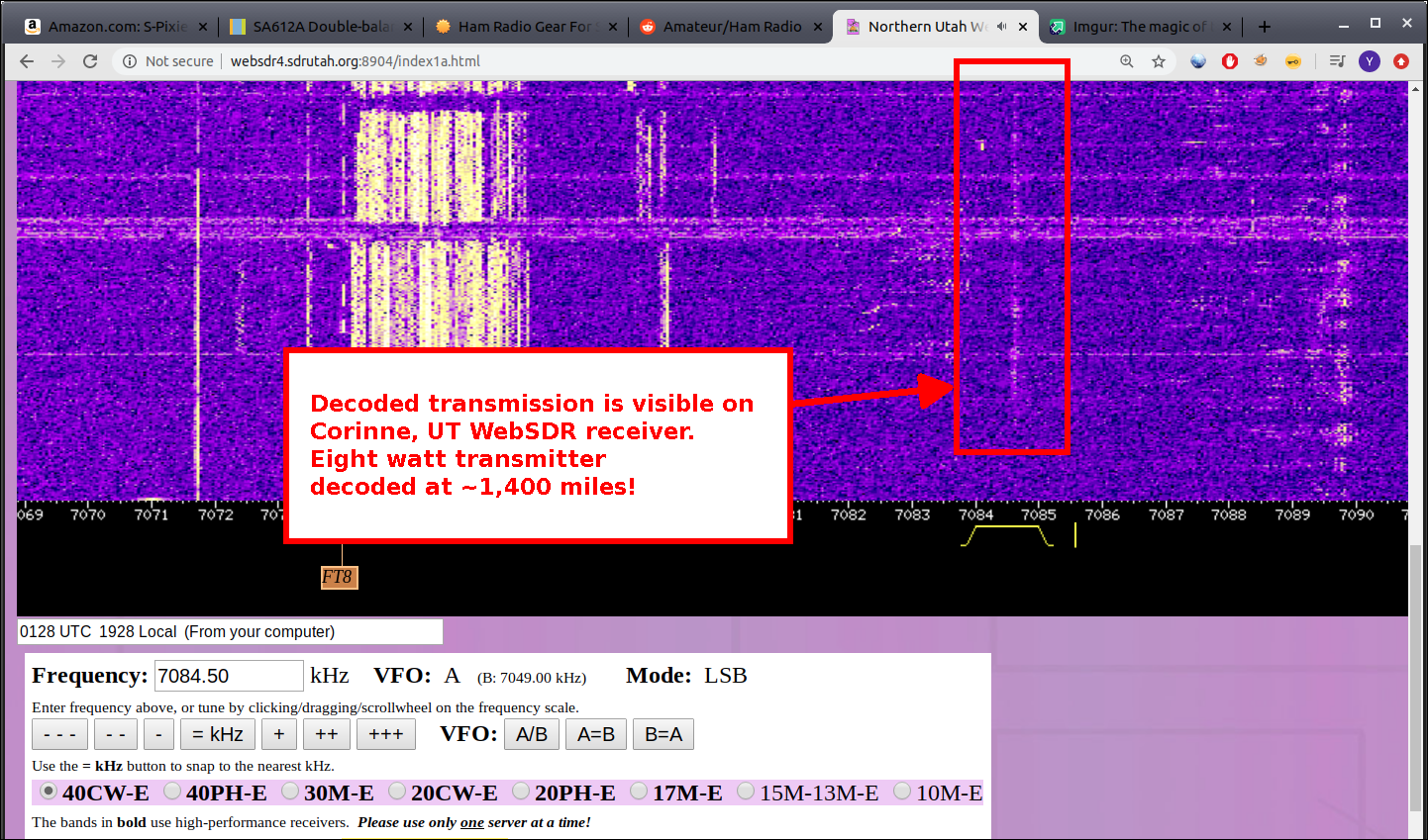
I’ve found that using WebSDRs is really helpful for testing. One of the best is the “Magenta” SDR at SDR Utah, which has a 40m beam pointed east from Corinne, UT. I was excited to see my transmission quite visible on the waterfall:
And when I used pavucontrol to wire up FLDigi to demodulate the audio from the WebSDR, I was greeted with successful receipt of my Hellschreiber transmissions:
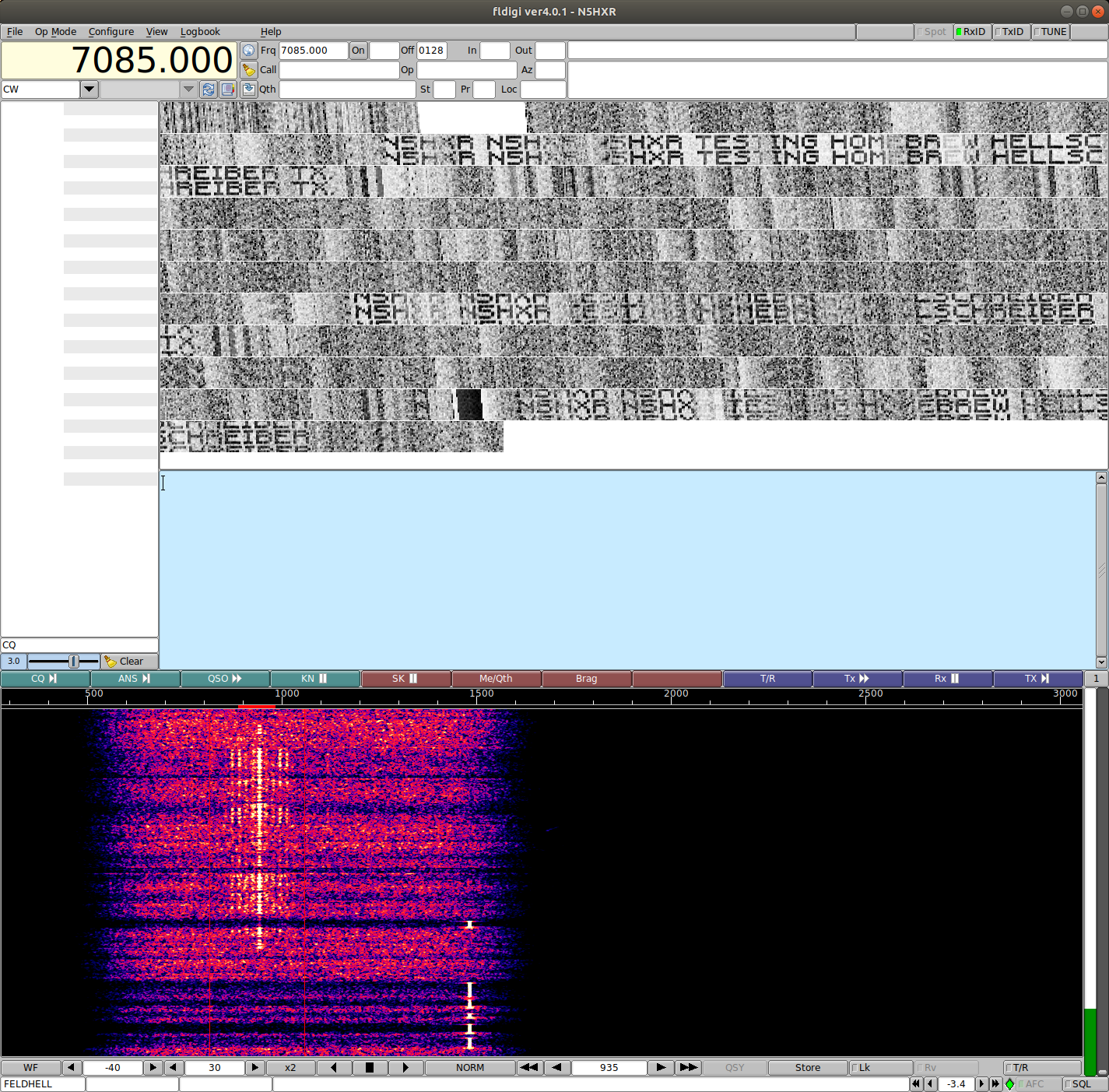
Making it to Utah from Louisiana with 8W is exciting. This is also a good test of a fully integrated transmitter… I can really feel things coming together for my longer-term project to build a full suite digital transceiver.
Conclusions
First, the amplifier works, and it is substantially more power. Depending on how I set it up, it’s giving me about 8W of output. If I can understand the thermal behavior, it might be possible to eke a reliable 10-12W out of it.
Second, the efficiency took a big dive in comparison to the previous amplifier. My measurements suggest it’s about 35% efficient, which was very surprising. I don’t yet know if this is because of some lack of isolation between the two IRF510s, a natural consequence of this bizarre “class D push pull” arrangement, or what.
Third, I need to carefully consider the “starting conditions” for these circuits in the future. Burning out the IRF510 and MCP14A0601 through careless firmware should be preventable by making the circuit more naturally resilient. I’ll have to think on it a bit.
Fourth, building things is fun, and it’s exciting to tackle new challenges, find new questions, and generally make progress to my future goals.
Next Steps
I need to explore this thermal behavior; without solving it, this isn’t the amplifier to use in my future transceiver project. I have a few other ideas for monkeying around with this design, but one obvious improvement is to switch to a genuine RF transistor. More amplifier playing to come in the near future!