Amplifier - solving thermal issues
Last time, my amplifier worked great. I did some testing on the air, got 8 watts of power out, etc. But one issue popped up – transmitting for a little while heated something up and produced some odd changes in power output and current consumption. With some gracious and patient help from some smart people, I’ve figured out what caused it, fixed it, and come out way ahead of where I thought I was!
Describing the problem
When I would key up the transmitter, the power amplifier would produce 8W. But after 5 seconds it would hit 8.9W; after 10 seconds, 11.42W; and at 19.8 seconds 13.1W! Worse, though, shortly thereafter, power would drop to about 3 watts, with an increase in current consumption.
It was my understanding that it shouldn’t be thermal runaway, since I am using MOSFETs. But I couldn’t really find any articles or discussions that matched what I was seeing. So I posted on QRZ, hoping the homebrew intelligentsia could help me out.
Answers obtained!
Things started to make sense when I went through all the things that get hot when transmitting. The output transformer gets pretty warm; the low pass filters got similarly warm. But what got really, really hot was the capacitors in the low pass filter…
The QRZ wizards suggested my capacitors were not spec’d for the voltage levels I was throwing at them, and probably not a type that’s ideal for RF. Since I just grabbed them out of a bulk pack I had sitting around (which doesn’t even include references or specs), that seemed like a pretty good working theory.
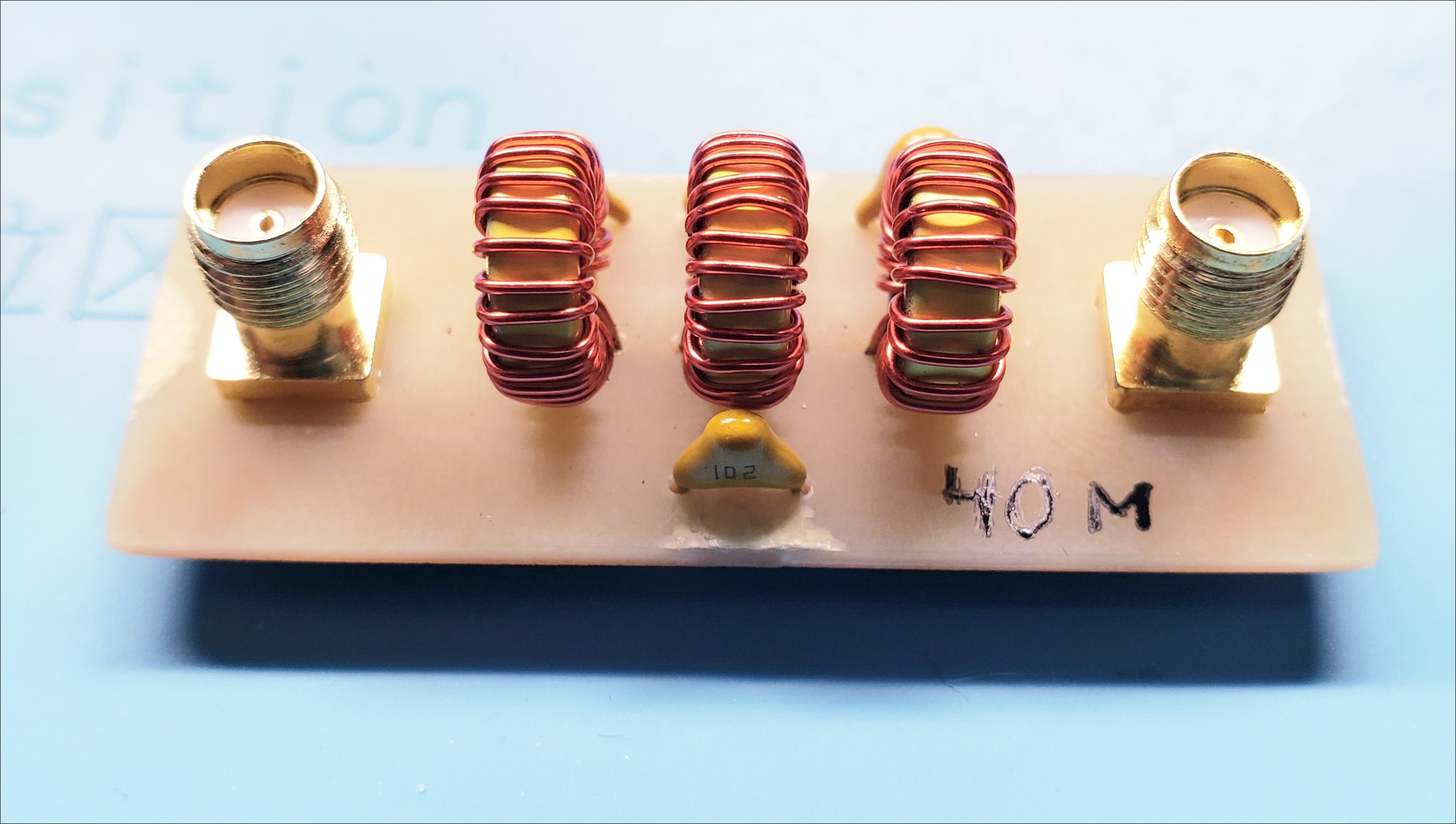
At the power levels I was seeing, voltage levels would be hitting 30-50v. So I needed to replace them with something better. Here is the “before” shot of the low pass filter:
And, since it will turn out to be relevant, my sweeps with the NanoVNA had shown somewhat lackluster performance (note the roughly 2.2 dB insertion loss!):
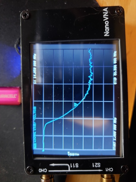
Apologies for the blurry image, it’s the only image I have from way back then!
Pretty blue capacitors
I ordered some TDK caps rated for 450v. They sure were expensive (as capacitors go), but the blue color looked nice. Mouser even upgraded my shipping to overnight, and they showed up the next day!
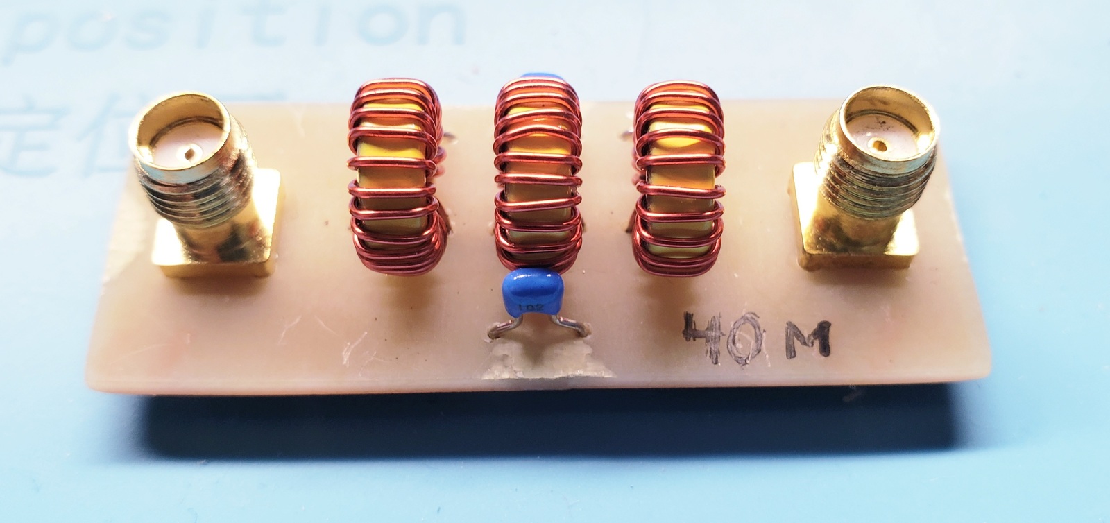
I removed the old yellow capacitors, and replaced them. Now the filter looks really snazzy:
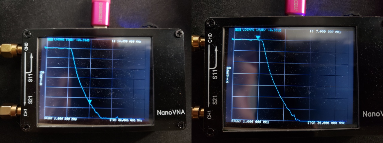
What was even more exciting was the VNA results. Only half a dB of loss at 7MHz, and a couple more dB down at the harmonics. The cutoff frequency moved up a bit, but not enough to be a problem. This is a useful experience for me – I’ll never use cheap capacitors in a filter again!
Testing with the transmitter
So, with initial indications suggesting this is now a much nicer filter, I attached it inline with the transmitter, and fired it up. I was greeted with this beautiful result on the oscilloscope:
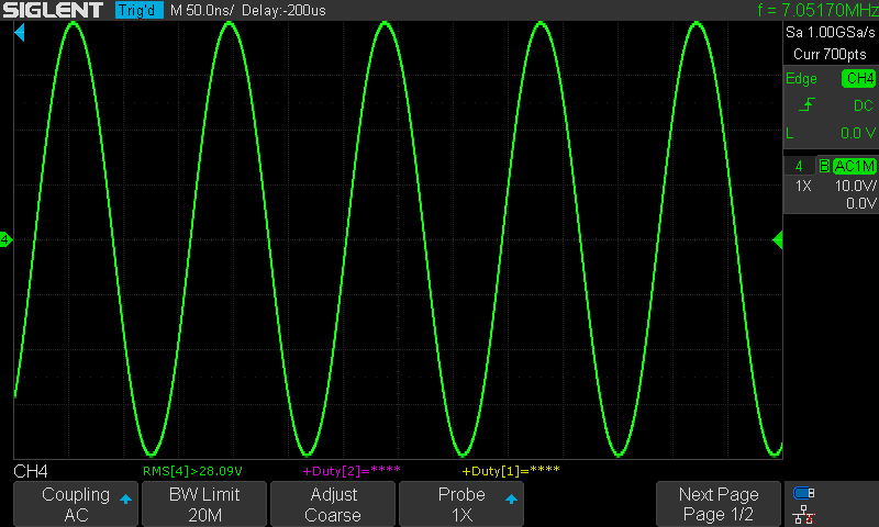
Just over 15 watts, and it was instant. No thermal variation – change over 30 seconds keyed up was less than 0.2 Vrms. I was so surprised initially, that I at first thought I’d left the dummy load disconnected. Nope, it was connected, and the measurement was real!
Conclusions
I will pay much more attention to voltage ratings on capacitors. And I need to buy a stock of new ones that are more suitable for RF projects.
And my amplifier works a whole lot better than I thought it did. I just couldn’t see it because of the inadequate low pass filter.
This design is simple, hits a much higher power level than I ever really planned for in my future digital transceiver design. There are still a couple things worth playing with on this design, but it should work well for a full-suite transceiver.
Finally, the satisfaction of hunting down, learning some things, and solving an interesting problem is great. I’m especially thankful for some of the online community resources available to me. I don’t really have anyone local I can ask these kinds of questions, and the willingness of others who know so much more than me to answer my silly questions is wonderful.
Next time might be receiver stuff!