RF Receiver Board
Moving on from amplifier experiments, I’ve gone and built a little RF receiver. It’s a direct conversion design, intended to produce output at line input voltage levels for use with a sound card or microcontroller ADC. This is another important step toward my goal of making a complete homebrew digital mode transceiver.
I have previously made a simple Tayloe detector, which was basically a copy of a few schematics I’d found (namely, a cross between the QCX and examples from NA5Y’s YouTube channel). It was quite successful, but I didn’t really design it, per se, and I can’t say that I knew much about what I was building at the time.
This time, I spent awhile reading up on direct conversion receivers, some new analog electronics material, and digesting the EMRFD and ARRL Handbook discussions of receivers. I was especially interested in this document by Mr. Tayloe himself, where he describes the theory of the mixer that bears his name.
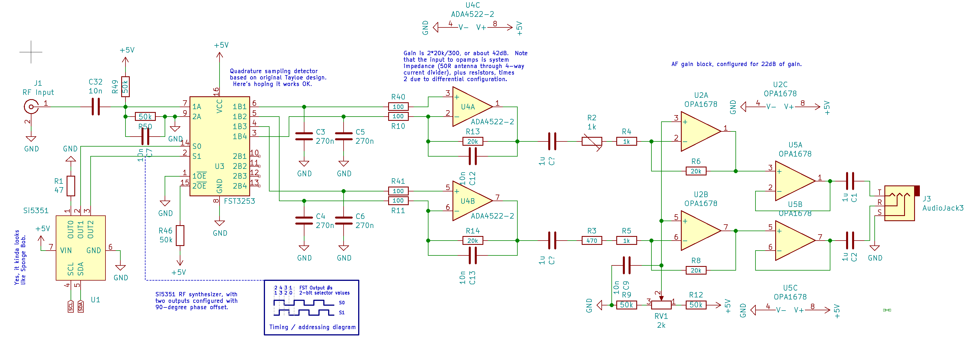
I decided to build the single balanced version in that document on page 6. In my first build, I just copied component choices from the QCX. This time I made a bunch of actual decisions, and might even know what their implications are. The schematic looks like this:
Sampling Capacitors
I decided to use a much smaller value for the sampling capacitors, since my goal is to be able to demodulate several popular digital modes. The QCX uses 470pF sampling capacitors, which makes sense for its CW use case. Using Dan Tayloe’s math [1] I estimated the -3dB point of the input low pass filter at 1/2*PI*270pF*300, or 1964Hz. I figured this would work better for digital modes that might take up some hundreds of KHz of bandwidth, centered around 1KHz.
I’ll note in passing that I’ve decided I will reduce the value even further to 220pF, adding another 500Hz of bandwidth. This is after examining the fall-off testing with the board I’m talking about in this post.
First gain stage
Reading this excellent article led me to thinking I might want to use a very low-noise instrumentation amplifier (I looked at the INA2332 initially, and later the INA818). It seemed like an interesting idea.
But after discussing it with one of the electronics subreddits, I discovered a potential issue with output offset voltages. This sent me into a spiral of opamp specification research, which I still find rather dizzying. In the PDF I linked, they do treat an instrumentation amplifier version – the authors point out that the inamp maximally isolates the gain stage from the antenna’s impedance, functioning as a much cleaner voltage amplifier.
Anyway, I grew concerned that I couldn’t properly understand what was going on with the instrumentation amplifier, and ended up choosing the more common differential amplifier arrangement. But, now armed with a bunch of newfound awareness of opamp specs, I figured I could make a different choice for my purposes than the LM4562[2].
I ended up going with the ADA4522, for better or worse. I still am not completely confident in my understanding of opamps to say whether it’s a great choice. But it seems to be working OK.
Total System Gain
The next big question I went to answer was, “How much total system gain do I really need?” I did some testing with my soundcard and signal generator to see what voltage level might be a minimum threshold for a line input:
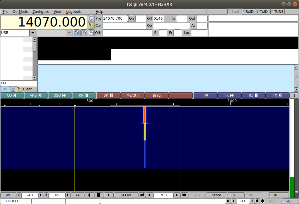
The first test was just seeing what showed up on FLDIGI’s waterfall. It seemed the smallest signal I could send (1mV) was quite visible. But I thought it might be useful to try some more rigorous testing. I recorded a number of WAV files at varying levels of line input voltage:
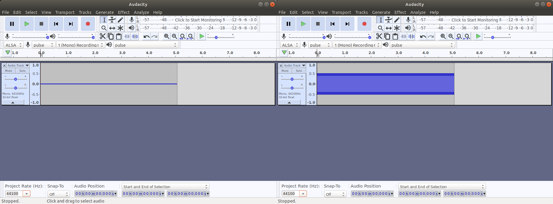
I then wrote a program to process the WAV files, extract the samples, and evaluate what range each exhibited in its 16-bit sample space. My goal was to get an idea of what line input voltage levels might cause clipping in the ADC. The result of running my program came out like this:
File                      Min     Max     Range   % of range
------------------------------------------------------------
line-input-0001v.wav     -19     19      38       0.06%
line-input-0010v.wav     -49     49      98       0.15%
line-input-0100v.wav     -379    381     760      1.16%
line-input-0300v.wav     -1119   1134    2253     3.44%
line-input-1000v.wav     -3676   3730    7406    11.30%
line-input-2000v.wav     -7383   7497    14880   22.71%
line-input-3000v.wav     -11282  11460   22742   34.70%
line-input-4000v.wav     -14718  14955   29673   45.28%
line-input-5000v.wav     -16508  16455   32963   50.30%
Based on the data, I reasoned that I only need to design the receiver with enough system gain so that the weakest signals I want to receive are brought up to a reasonably detectable level, while keeping the strongest signals from clipping. It seemed that a lot of what I read suggested that more care is necessary for nice volume levels in a speaker or headphone output, but my testing suggested that an FFT doesn’t really care that much what the average level is – just that signals be detectable.
Well, that left me with questions, whether this is the right choice. EMRFD, for example, suggests something like 90dB of system gain for a receiver – very different from the ~65dB I thought I’d need to get S1-S9+ signals into my ADC range! So I posed the question on the QRZ forum, and got some interesting feedback.
Basically, what I learned was that in real life I would want to consider AGC, as I might really encounter signals 40-60dB above S9. But for a first experiment, my thinking seemed sound enough to proceed, so I went forward with the idea of achieving about 65dB of gain.
To accomplish this, I set the first gain stage for 42dB of gain (feedback resistor is 20k, over a 300 ohm input, times 2 for differential configuration). The second gain stage, using OPA1679 opamps, I set for 22dB of gain with a 20k feedback resistor over 1470 ohms input. This makes for a total of 64dB, in theory.
Biasing and analog stuff
The scary part for me is that I never quite know what to do with opamps when it comes to biasing. I went with my best guess, based on reading up on other schematics. LTSpice suggested I might not need a bias at the MUX input, but one of my mentors suggested otherwise. I still haven’t tested to see if it stabilizes on Vcc/2 without the bias (as it happens in LTSpice), but it seemed prudent to rely on elmer wisdom. I also noted that Dan Tayloe always puts a bias on his detectors :-).
The initial build did not include the two capacitors marked “C?” in the diagram above. The need for these was determined experimentally, as I found that the difference in bias between the two opamp gain stages was enough to peg the outputs. I had even included RV1 for tweaking bias level, but it didn’t give me the range I would have needed to make them the same. Alas – I cut traces and added the “C?” capacitors, and everything was fine.
Opamps continue to frighten me.
Construction
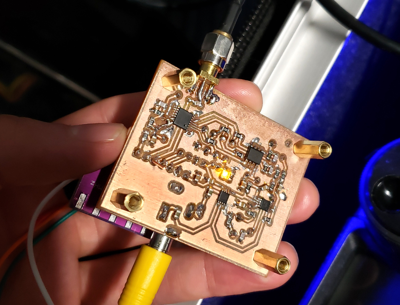
The board milled OK, but I had a little nightmare with the FST3253. While trying to get it straightened, I acted too hastily and ripped up a couple of the traces. The damage was quite severe. The following photo shows my bodges to make it all come out OK:
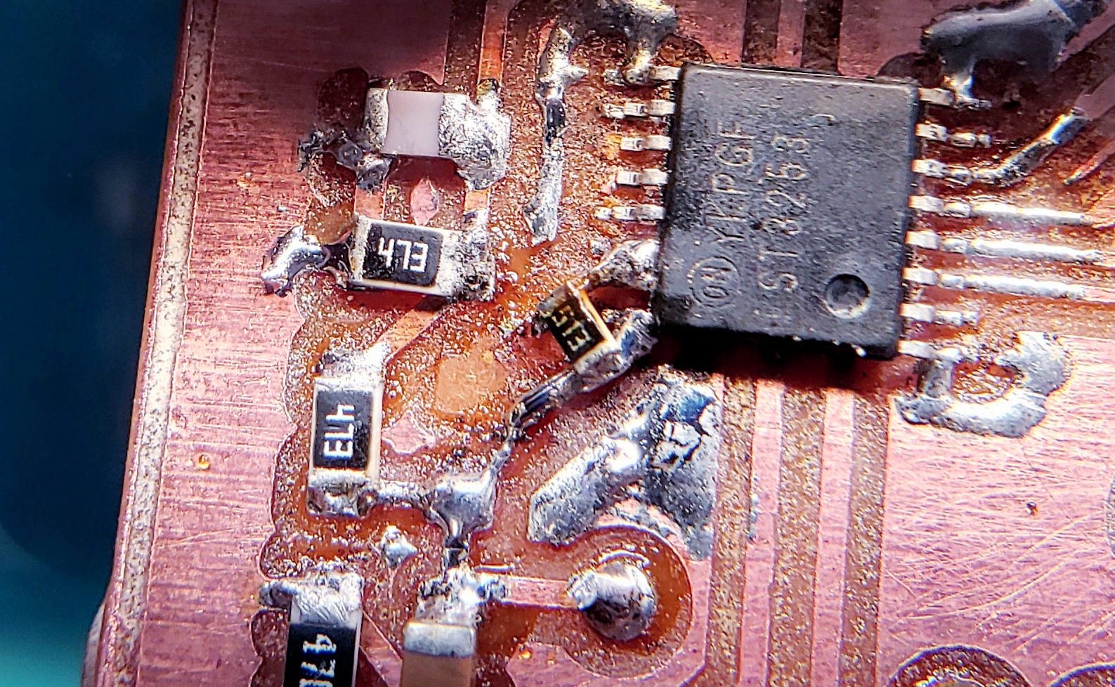
As can be seen, I had to solder (tiny) wires to two feet on the FST3253 to get them attached to the right traces. Finally, I had to carefully bridge those with an 0603 resistor. I’m glad that the circuit doesn’t use the second channel of the MUX, or I might have had to scrap and recut the board!
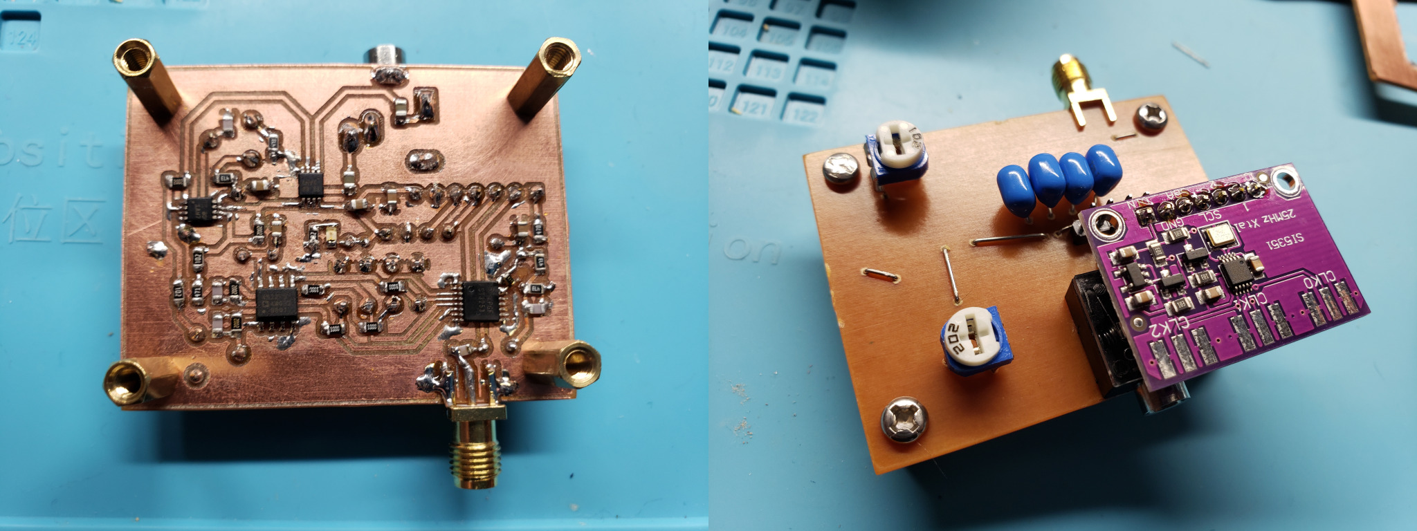
Anyway, once things were assembled, the final result came out looking pretty good:
Immediate Testing
Without any ado, I attached the board to my 84’ random wire in the front yard. After a little frustration identifying the afore-mentioned issue with missing capacitors (added the “C?”s), I could hear the glorious wail of FT8 in my headphones. And very loud too; I guess the gain was doing OK!
The first moderately-rigorous thing I did was to put together a GNURadio flowgraph to bring in the audio as I and Q samples, and show the results on a waterfall and graph.
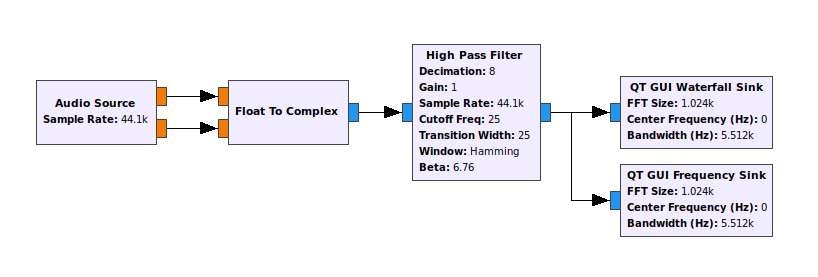
All this does is assume that I have I and Q set up right, unite them as a complex signal, filter off any DC noise, and display it. I was overjoyed to see sideband isolation (suggesting that I and Q are properly phased), and lots of obvious signals:
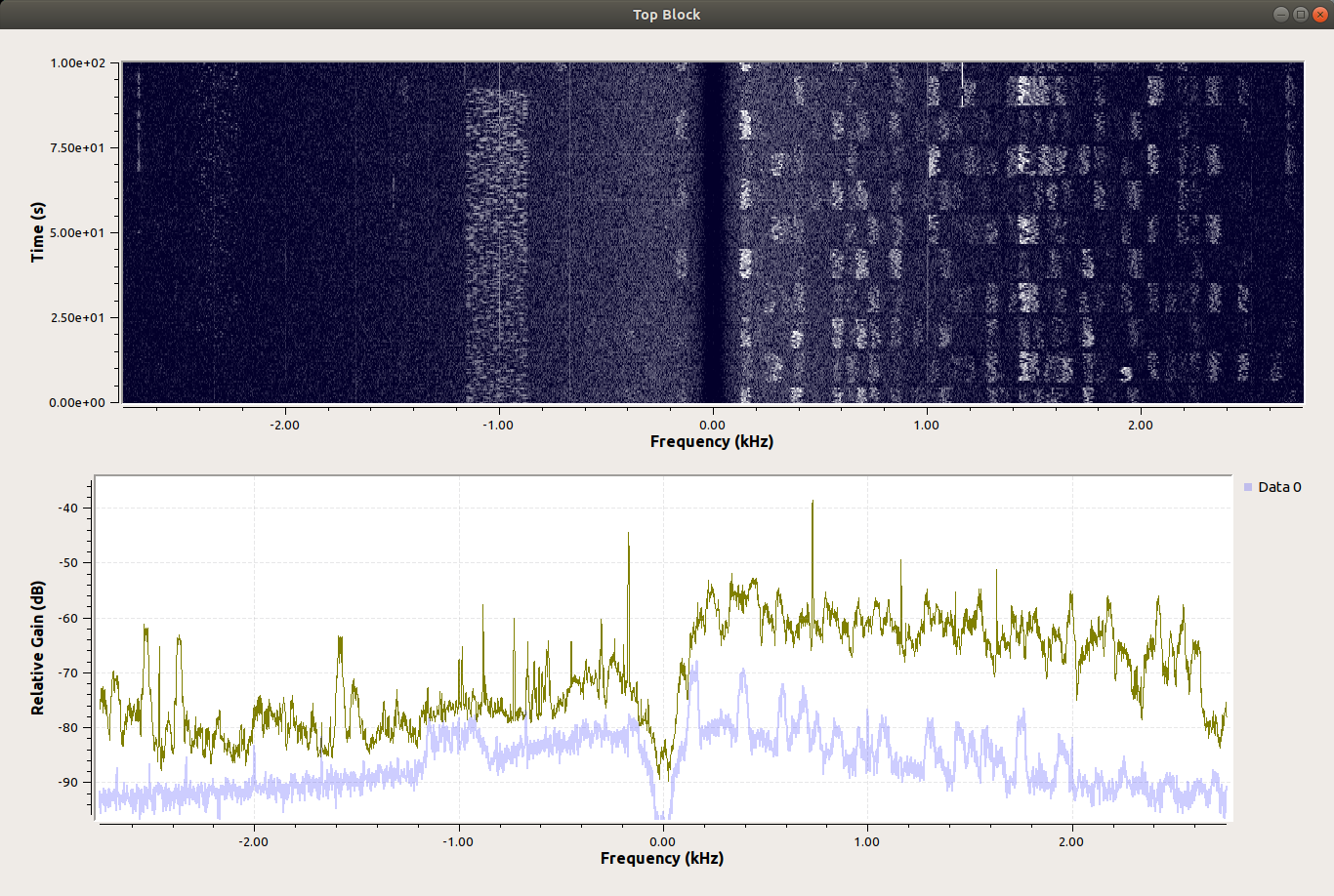
In this image you can clearly see that the lower sideband has some digital mode signal (Olivia maybe?), and the upper sideband shows gobs of FT8. Nicely distinct from each other! I ran this for a few hours and monitored signal levels and things. It was a great result to start out with.
WSJT-X Demodulation Testing
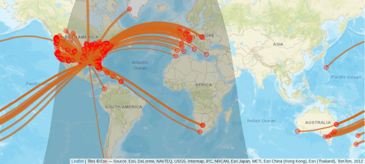
Seeing as how I was clearly seeing signals, I wondered how demodulation might go. I connected the audio to WSJT-X (without sideband elimination, it’s like a double sideband receiver), and ran WSPR for a couple weeks. I saw lots of decodes on the 40m band, from all over the world:
IQ Balance Testing
I connected my signal generator to the receiver, and the output through my new TRS to double coax adapter to the oscilloscope, and wanted to see how my trim adjustment for IQ balance would work. For best sideband rejection, I need to get the two signals pretty close.
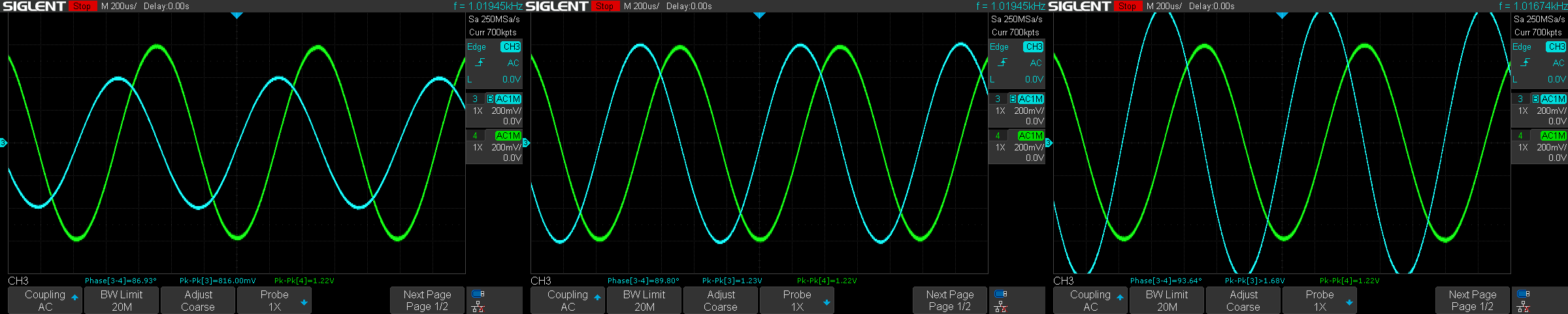
The results show plenty of range to adjust the balance (so my choice to put it where I did wasn’t crazy!).
Gain Testing
While I had it on the oscilloscope, I thought I’d evaluate what actual gain I’m getting. By setting up the system with some attenuators[3] I was able to clearly observe about 60dB of gain. So somewhere in the system there’s a few dB of loss (or mistakes), but I’m pleased to see that I nearly hit my target gain of 64dB.
I found that I could clearly observe 1uVpp signals in the output. I don’t have enough attenuation to go lower than that, but this testing suggests I might be able to receive S0 signals, if the atmosphere and my neighbors let me get them here. Clipping hits at an input voltage of 5.2mVpp. If my math is right, that indicates I can accept up to S9+30dB inputs without clipping (though I suppose there might be some compression at that level? Need to test that, I suppose).
Conclusions
- It’s a lot of fun to learn, design something, build it, and see it work. Especially when it has opamps in it.
- I found that this board is vulnerable to noise. It’s not shielded at all, and there are some isolation problems between the stages, plus a lot of noise if I power it from a regular USB port. I’ve begun reading up on how to properly shield and isolate things.
- The QRZ wizards suggested I can’t really make a useful receiver without AGC. Well, I read up on AGC, and wow, what a complicated topic. For now, I think my next receiver will just have a switchable attenuator at the front. Someday I’ll revisit AGC.
- The gain level is fine, but I think I’ll target a slightly higher level for the next revision to make sure that small signals are far enough off the noise floor.
[1] I noticed that some online resources use the wrong math to calculate the gain of the first stage after the detector. Mr. Tayloe points out that the impedance leading into the opamps is a combination of the antenna’s impedance and any resistances added by the designer. But we need to treat the MUX like a 4-way current divider. So a 50 ohm antenna becomes a 200 ohm source impedance – add the 100 ohm resistors to that, and you actually have 300 ohms for the signal on the way in. These figures were confirmed in my testing, determining actual total system gain. Some online resources state the gain using only the input resistors, apparently forgetting (or unaware of) the influence of the antenna’s source impedance.
[2] I say “different choice” not to imply that Hans Summers chose poorly in the QCX – he is very clear that he made choices based on pricing and ease of use, and readily admits that other opamps might perform better. The one I went with is more expensive than the LM4562 ($1.67 vs $4.42), but with some compelling specs!
[3] Probably not the most precise testing. All I have are cheap 10dB attenuators from Amazon. Someday I’ll have nice things :-).