Testing the BGA2866 MMIC amplifier
I’ve had a very hectic summer, thus far, with some vacations, house renovations, and other excitement. So it’s been awhile since I wrote up a blog post. Actually, it’s been awhile since I built anything, ugh! But today I put together a small test board to exercise the BGA2866 MMIC amplifier, and the details are what’s in today’s post.
Introduction
I’m working on a simple direct conversion transceiver. In some ways, it’s actually less interesting than some of the other projects I’ve done, but I feel that it’s an important baseline project for me to complete before I jump into more complex whole transceiver projects.
One of the boards I put together (blogged about it here) recently used a BGA2869 MMIC amplifier in front of a MiniCircuits ADE-1+ diode ring mixer. I ran into some trouble with it, and after asking about it on QRZ a bit, some of the wizards seemed to be suggesting it’s not a good choice anyway.
The criticisms were several: (1) there are oscillation and stability issues without special construction considerations, and (2) the input IP3 is too low and compromises the dynamic range of the receiver, and (3) these are too much gain for an RF preamp on a DC transceiver. I was able to defeat objection #1 by applying some ferrite beads, though how much this affected the performance of the amplifier I could not easily tell. The second objection sent me on a long research project, trying to understand what IP3 really is, and why I might care.
A test board
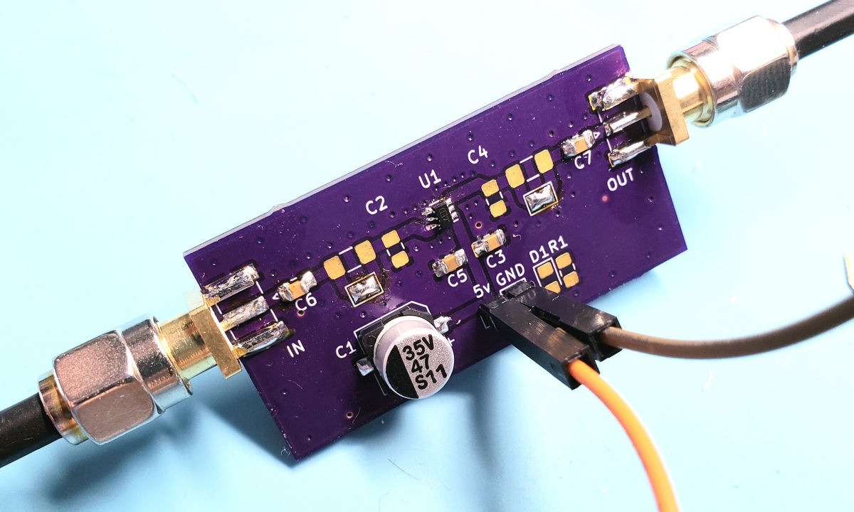
I eventually decided I needed to isolate the BGA28xx amplifier module from the rest of the receiver circuit and take some measurements. I whipped up a test circuit shown below. Not all the parts in the schematic are intended to be installed – e.g., the ferrites are there only so there will be a footprint to install them on the PCB if I decide they’re needed:
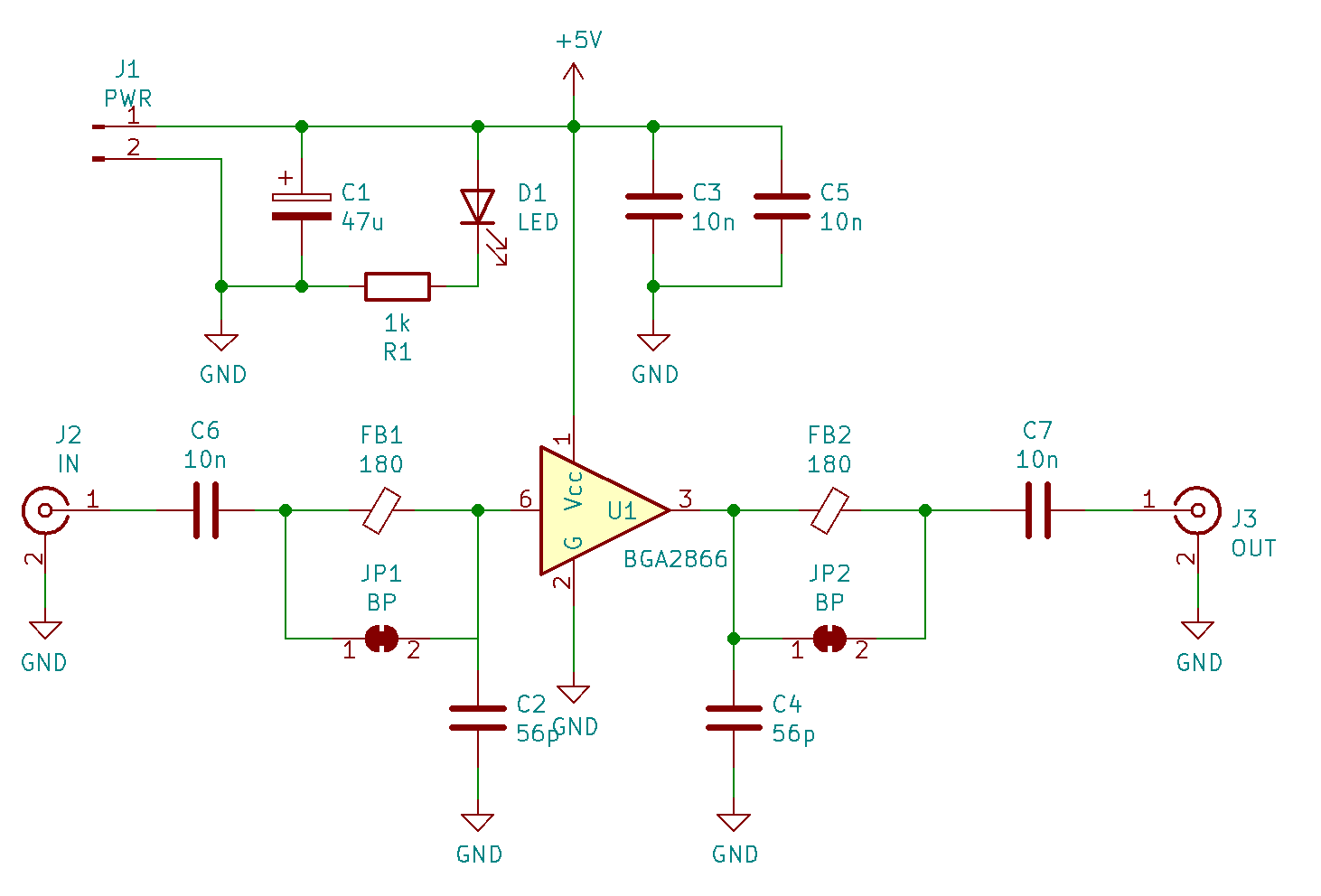
I wanted to pay special attention to the footprint on the MMIC. One of the QRZ commenters said the lower gain ones were more stable, but also needed to have lots of vias to a solid ground plane. I can’t do that on the mill at home, so I ordered a board from OSHPark. And…. then I ordered another one when those arrived and I realized I’d forgotten to actually put a ground plane on the back (sigh).
The result is shown above, fully assembled with the BGA2866 (the variant of the BGA28xx chips that has the highest IIP3 listed in its datasheet).
Discovering what IP3 is
I spent some time reading about IP3, trying to decide (A) what it means to me for this project, and (B) what level of IP3 I might care about to make an acceptable baby’s-first-receiver.
I’d read about IP3 in passing before, and never paid it much mind. After playing with some of my amplifiers and measuring IP3, I’m coming to a decent intuitive sense for what’s going on. Any non-linear device in my signal chain will produce intermodulation products. With multiple signals coming in, this manifests in a mixing behavior, where sum and difference products appear in the output.
The issue, as I now understand it, is that if I’m trying to listen to some weak signal, but there are other, powerful signals entering the receiver, the resulting products might compete with the signal I want to hear. Since my receiver will be exposed to at least the entire 40m band at the front end, then all that needs to happen is someone nearby or using a lot of power randomly clobbering my chosen frequency, and they may frustrate my attempts to zero in on weaker signals.
The IP3 metric (the intercept ponit of third order intermodulation products… whew, glad it’s got an acronym) is the level of two signals coming in that produces intermodulation products that are the same power as the original two signals. The mixer I’m using is an ADE-1+, which MiniCircuits says has an IP3 of +15dBm (owing to the distortion produced in its diodes). If I put an amplifier in front of that mixer that has a lower IP3 value, then it will create unhelpful intermodulation signals that wouldn’t be there otherwise – the opposite of help.
My first thought was about all the SA602-based DC receivers I see in others’ projects. The datasheet for that mixer says it’s got an input IP3 of -13dBm. So that’s almost 30dB worse than the mixer I’m using. And, to be honest, one of the biggest complaints people have about the SA602 seems to be its susceptibility to front end overload and poor performance near loud signals.
So, lest I knowingly make a radio that has similarly bad performance to a lot of other ones that people complain about, I decided I should take the QRZ wizards’ advice, and take IP3 seriously.
Measuring the BGA2866
I was curious how the BGA2866 might look at HF, since the lowest frequency that figures are provided for in the datasheet is 250MHz. In addition to IP3, I was curious about gain figures, since I wasn’t sure where the trend line should go in the datasheet graphs. After all, the test fixture NXP used to characterize it was clearly intended for its VHF/UHF application.
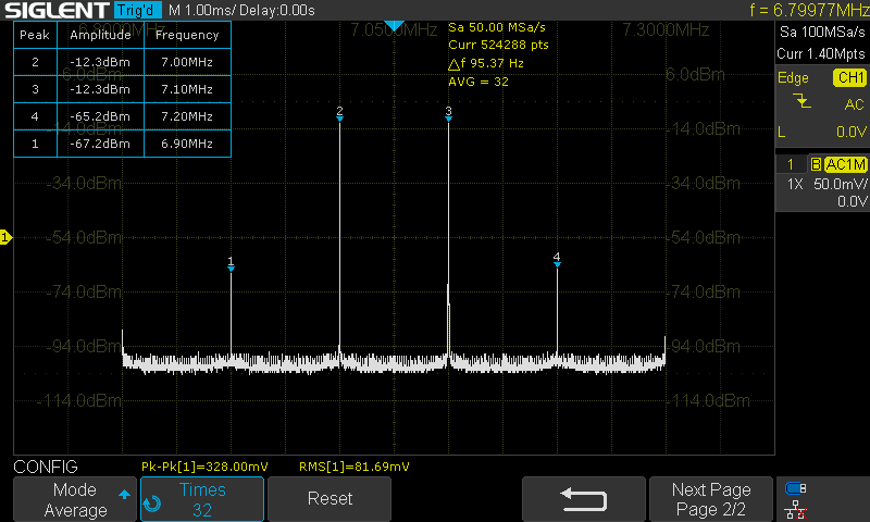
I set up my Siglent signal generator to generate two signals – one at 7MHz and the other at 7.1MHz – and attached that to the amplifier input. From there, the signal is amplified, and goes across my oscilloscope, and into a 50 ohm resistive dummy load. The following image shows the output from my scope’s FFT capability:
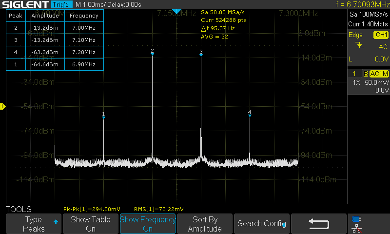
An IP3 measurement assumes that intermodulation products increase at a certain rate (3dB for every 1dB of the fundamental), so the intercept can be calculated from a measurement such as is shown above. I used this online calculator to run the numbers, and obtained the following estimate for the output IP3:
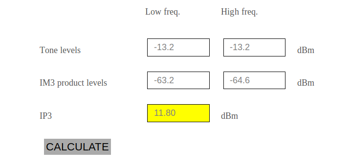
I then took a measurement of the signal directly from the generator, and calculated the gain as 18.5dB. So the input IP3 is -6.7dBm, which is just a tad lower than the minimum expected value in the datasheet. I suppose this is a “worst case” measurement, since I know I don’t have the best equipment to measure with.
The gain is described to be about 24dB, though the datasheet figures show it tailing off at low and high frequencies. Still, 18.5dB is quite a bit lower than expected. I don’t think I’ve done anything in this super-simple test circuit that would compromise the gain, so perhaps this is just a consequence of use well below the intended frequency range. If someone with knowledge reads this and can fill this detail in, please let me know!
Higher supply voltage
I noticed in the datasheet that the BGA2866 works up to an absolute max of 7V supply voltage. I wondered what would happen if I pumped it up to max, so I took some measurements there too:
This comes out to 19.4dB of gain, with an IIP3 of -5.2dBm. It’s slightly better, though I don’t imagine I’d care to complicate my power supply circuitry for such a small improvement. The IP3 does get substantially worse as the voltage drops toward the low limit (4.5v), and moreso at 4.0v, which is the least I tested.
Conclusions
I was able to build a BGA28xx test board that didn’t require ferrite beads or other black magic to achieve stability. The gain of the chip and input IP3 came out roughly in line with the datasheet figures – 18.5dB of gain, and -6.7dBm IIP3.
Since I want to take the recommendations I’m getting from those wiser than I am, I guess it does make sense not to use this chip at the front end of the system. Perhaps with some other architecture it could have a place. But as it stands, putting this in front of my mixer would drop the intermodulation performance by almost 22dB, which does seem like a lot.
Experimenting with different levels of input, I could imagine situations on the 40m band where I’m trying to read some signal at, say, -90 or -100dBm. All the loudness of FT8 not too far away could absolutely generate some signals nearby that could cause problems for me.
So the next step is to try a different front-end RF preamplifier. I want to have something there, per the recommendation of Wes Haward, et al., in EMRFD… it just needs to be a better performing amplifier.