IQ Phase Detection
Continuing from my last post, where I built a digital IQ modulator for generating a carrier at any amplitude and phase… this post is about some investigation of phase detection and demodulation. I carried out three separate experiments, which make me hopeful that I could actually build a non-coherent demodulator for low baud-rate amateur radio digital modes.
Premise
Consider an incoming carrier wave – let’s mix it with a matching signal, but set the phase to a few different values. When multiplied in a mixer, phase differences produce a change in average value: a DC offset. See the following graph, which shows three products:
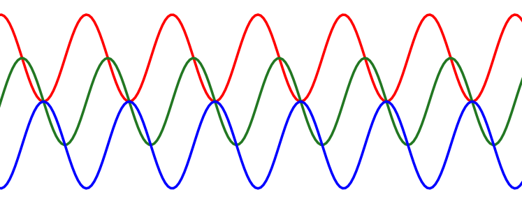
The red signal is the result of mixing a carrier and local signal with a 0-degree phase difference. They’re the same signal, and notice that the average value rises, which would be analogous to a positive DC bias.
The green signal shows what happens when we mix the carrier at a 90-degree offset. The result has the same average value, though there is obviously a change in phase.
Finally, the blue signal shows what happens when we mix the carrier at a 180-degree offset – the signal is flipped vertically. We get a negative average value, which would be a negative DC bias if this signal was electrical.
So I thought maybe I could tune a local oscillator to the same frequency as an incoming signal, and measure its DC offset coming out of the mixer by filtering off any high frequencies. Put another way, I’ll take the output of the mixer, filter off the addition products, leaving the subtraction products, which is a “signal” at DC…
First attempt
I pulled out my double balanced diode ring mixer I had made for a previous project, and injected a signal from my IQ modulator I made in the last post. I was really excited to see obvious DC biases, and that phase reversals were quite evident. Here is one of the better scope traces I generated:
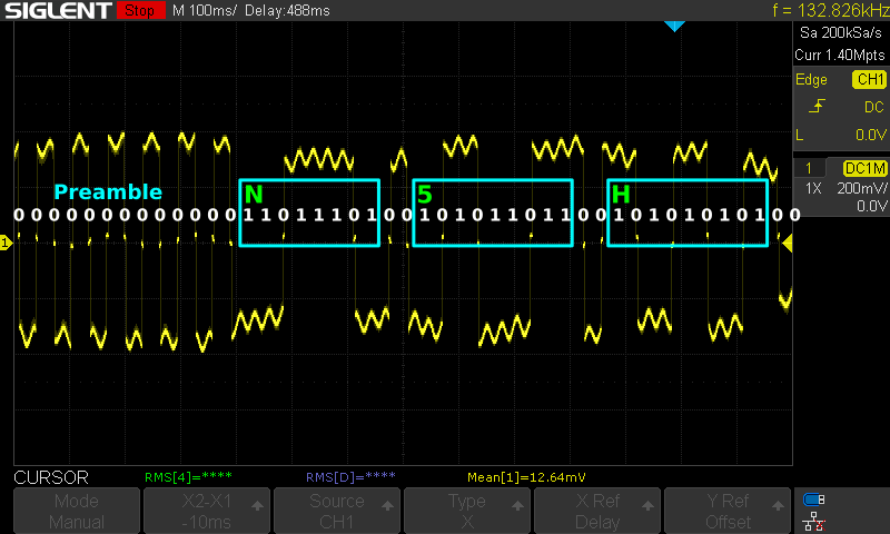
On the one hand, it was pretty clear I could make out the transitions. Demodulating PSK31 is quite easy – in any given symbol period, if the phase changes, it’s a 0-bit; otherwise it’s a 1-bit. But I did say this was one of the better examples… there were some worse ones too.
The problem is that the DC biases disappear when the carrier and the LO are close to 90-degrees phase angle to each other (the green line in the graph above). But, if that happens, I can just make this thing an IQ mixer, and mix twice, with two local oscillators in quadrature (90-degrees apart).
But do do that, I’d have to build something…
IQ Mixing
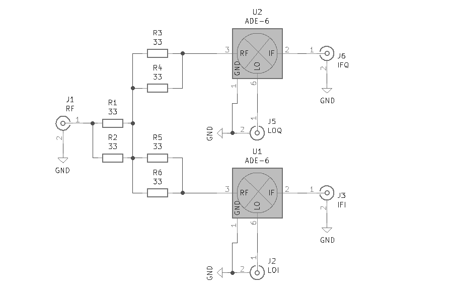
I rummaged around in my parts bins, and came upon my last two ADE-1+ diode ring mixers from MiniCircuits. These would be perfect – in addition to having much better performance than my scratch-built mixer, I can put both of them together for a single IQ mixer module. It’s a simple circuit:
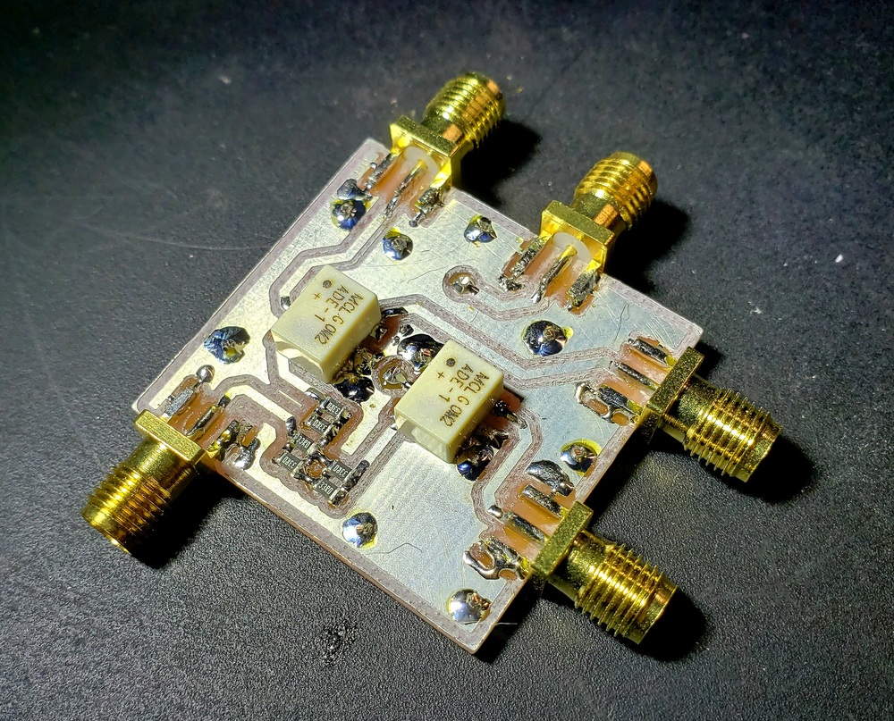
I milled the board on a double-sided PCB, so I could stitch a ground plane under everything for best signal integrity. Even though this is a pragmatic experiment for testing something out, it seemed like I might need this for other things in the future, so I’d try to do my best. It came out quite nicely:
This mixer also has a built-in 6dB attenuating splitter. This way I didn’t have to wind any toroids or worry about balance issues. In a real application, I might just as well do it this way anyway, as this detector will come after the RF front end, IF filtering, and gain stages.
I generated some PSK31 signals, and was greeted with a beautiful result. Using my oscilloscope’s XY mode, the DC bias for I and Q outputs creates a great constellation diagram in real time:
There is some unwanted phase rotation coming from phase noise, jitter, and tuning errors. It is still quite possible to observe the phase shifts, though, and the distinctive pattern of PSK31 is evident: a preamble of 0-bits, transmitted data, and a postamble of 1-bits at the end.
I communicated with some of the folks on the RF Electronics subreddit, and learned a few things. One issue they raised was that a lot of PSK demodulators do coherent demodulation, where they achieve a local carrier lock on the incoming signal to stabilize the constellation (i.e., avoid the unwanted phase rotation you can see in the video). Without that, the unwanted rotation might be an issue.
But I was pretty sure that amateur radio baud rates are slow enough that as long as the unwanted rotations are substantially slower than symbol changes, it should be possible to achieve a simplistic carrier recovery without adding the extra circuit complexity. At least one of the users on the subreddit agreed, but there is definitely a chance that I’ll have to get more complicated if things don’t work out!
A DC-bias preserving IQ phase detector
I set about trying to find the best way to preserve the DC offset of the mixer products. In all of the receivers I’ve built so far, I’ve peppered the RX chain with DC blocking capacitors and added bias when needed, which was all so simple. But keeping the bias… that’s a new problem for me!
I played with a bunch of ideas with instrumentation amplifiers, or summing amplifiers with a buffer and inverter, etc. I don’t want to splatter my circuit with a ton of extra opamps, though, so I wanted to find something more elegant. One line of inquiry included unbalancing a diode ring mixer by applying bias to the diode ring – and indeed, that bias seems to be preserved in the output, but one of my mentors cautioned me about the consequences of unbalancing the mixer.
Nevertheless, the LTSpice simulations were encouraging… I reread one of the most linked mixer docs on the Internet, and had a little burst of inspiration. There is no need to have a full double balanced mixer, with two transformers, and so forth. I thought I could perhaps modify a single-balanced mixer to have and preserve a DC bias on its output, and the following schematic emerged:
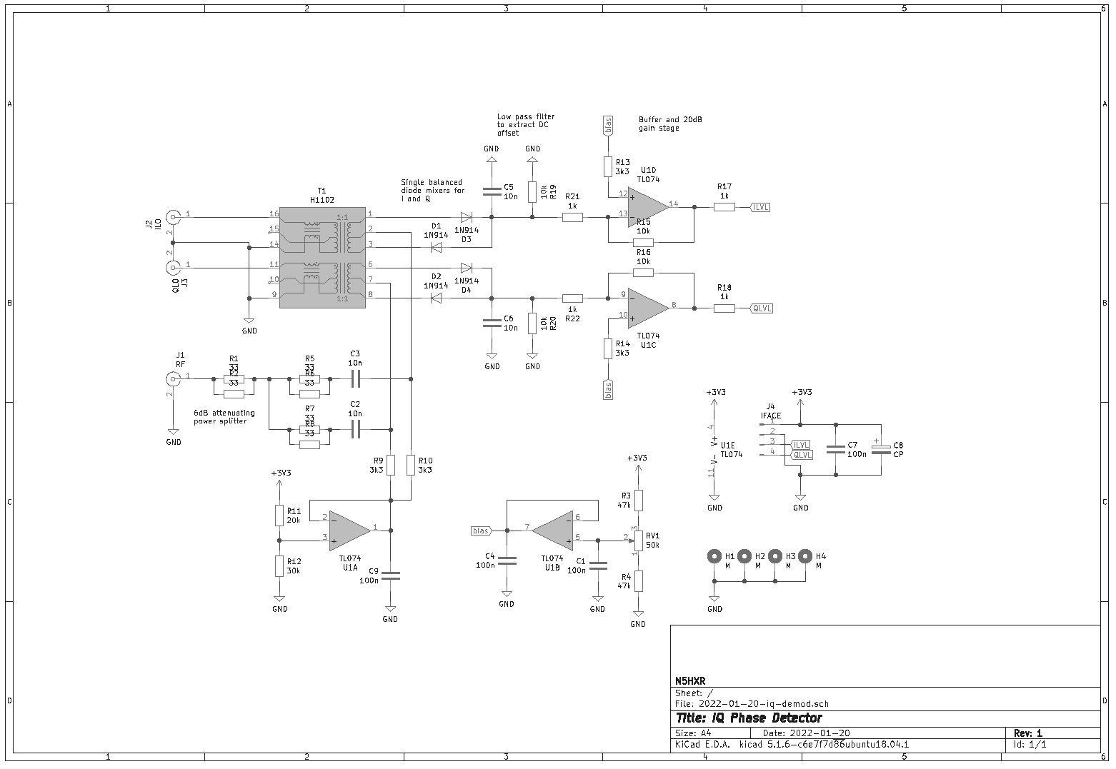
Simulations in LTSpice were very encouraging. The LO signal does make it out the IF port, but since I’m filtering the output hard for the DC offset, it seems to become kind of irrelevant. I went forward with this design, crossing my fingers – I don’t have a very good track record yet when I charge off into unknown territory; since I haven’t seen any examples of this strategy, I felt like it was a bit of a long shot.
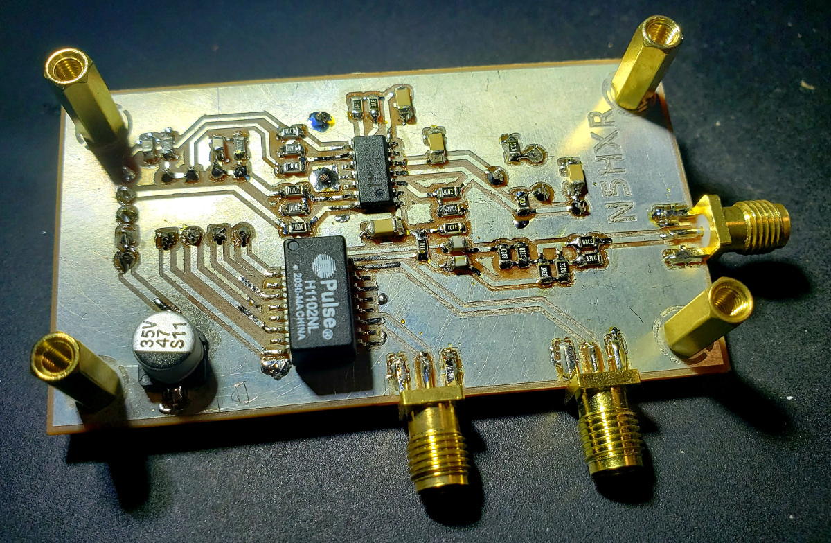
This was another excellent opportunity to use these little H1102NL ethernet transformers. They’re super cheap, coming in around $0.20 each. Every one of them contains two transformers, so I have all the transformation I need in one package for this circuit. No winding toroids, no balance issues, and bandwidth up to 100MHz. Pretty cool!
I did have to think through some of the bias situation. The output bias includes some drop from the diodes, so I set the bias input to the mixer to 3V, and then made the input bias point for the opamps variable. I figured I could scoot the level up and down to bring the two biases together at run-time (spoiler: this turned out to work fine!).
Testing the IQ Phase Detector
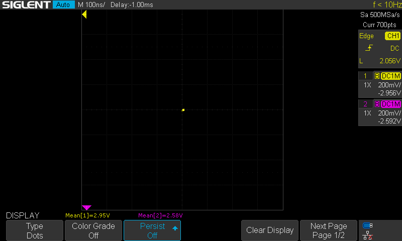
I set things up with a quadrature LO, and using my FT-891 and FLDIGI to send signals. With no input signal, I saw the following output in XY mode on the scope after adjusting for level:
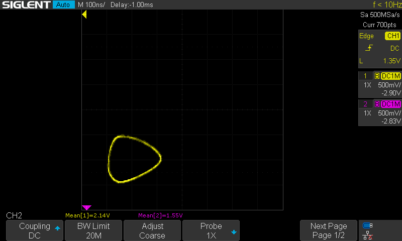
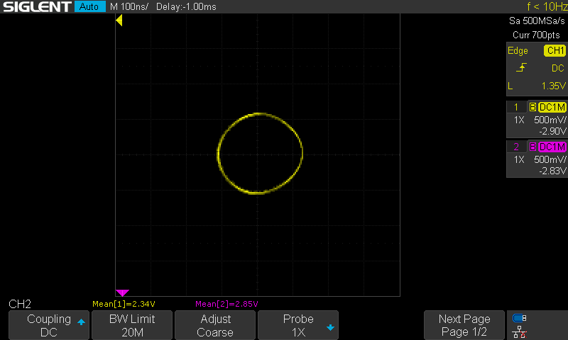
When I injected a signal, and without tuning for a frequency match, I saw a quirky “circle” as the constellation diagram:
By adjusting the trimmer potentiometer to move the gain stage bias around, I could easily enough find the corners. Here is setting the bias too high, showing the opamp rail getting in the way:
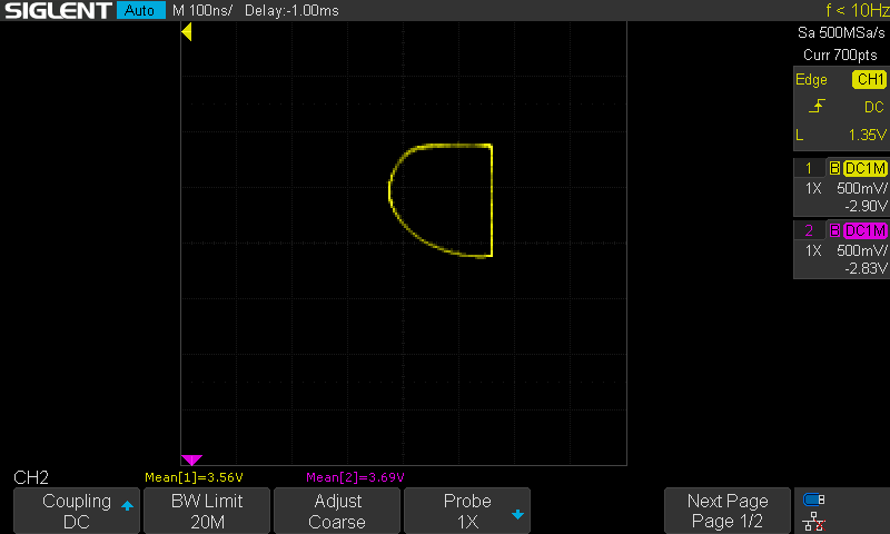
And here’s a nice goldilocks level where the constellation diagram is not overly distorted, and there’s a lot of range on either side. A pretty good match!
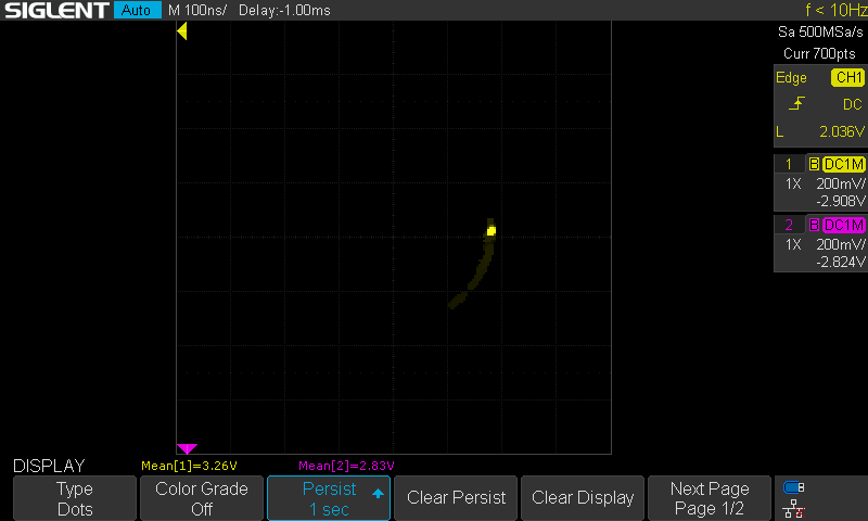
Now I could adjust the LO for a good tune on the incoming signal, and started to see rotation in the diagram. It was exactly as I had hoped it would be. Of course, due to jitter, phase noise, and other variation I can’t get a good frequency lock, per se. But it’s possible to get within 1Hz, and see a sort of lazy random walk around the circle:
And now for the ultimate test, I thought I would generate some PSK31 signals from FLDIGI and see how they looked. The following video shows a couple transmissions of PSK31, followed by one attempt with a QPSK mode where you can clearly see the square-shaped constellation graph:
Conclusion
Playing with this hardware is giving me some confidence that I think I could use hardware to do some of the heavy lifting, and build a PSK31 receiver. By doing it this way, I can avoid the complexity of carrier recovery, and use a smaller microcontroller that shouldn’t need a lot of DSP capability.
With a couple more experiments to work up an IF chain for a superheterodyne architecture (front end filtering will be a real challenge to get enough selectivity!), I might be pretty close to building my next transceiver – a home-made PSK31 transceiver, with no computer required. Building things and seeing them work is such a thrill.