Variable Attenuator
My son and I are starting a project to build the ultimate ham radio cyberdeck. Of course, this will require a custom HF SDR, so my head has been filled with ideas. I’ve built an IQ modulator for TX, and a few different IQ mixers for RX. And of course, I’ve got a halfway decent QRP+ HF power amplifier that I realize I haven’t written up here yet…
But a few pieces remain slightly outside my repertroire to put it all together. This post is about experimenting with a Waugh attenuator, which is the design used by the IC-7300 for AGC. If I want a real AGC in my primo cyberdeck, I have to work something out, and this seemed quite promising!
A spark of inspiration
Someone on an Internet forum asked a question about the IC-7300’s AGC. It piqued my interest enough, I thought I’d look at the schematics. There, on page 11, I found the AGC is built around a variable attenuator just prior to the ADC inputs:
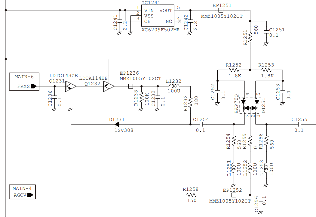
That little BAP70Q intrigued me – a single device with four little PIN diodes in it. And the datasheet calls it a “quad PIN diode attenuator”. I hadn’t really seen one of those before, so I started reading.
The four-diode PIN attenuator was evidently invented by Ray Waugh, an anti-patent HP engineer of yore. He improved the former three-diode version, and it caught on. It’s apparently the most common variable PIN attenuator design. The diagram at that link comes from HP’s AN 1048:
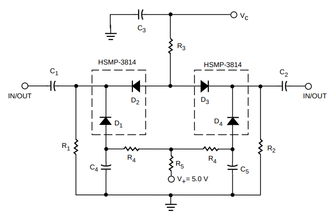
I rummaged around, and didn’t seem to have any decent PIN diodes… but then I remembered I recently bought a big stack of 1N4007s. Despite being rectifier diodes, it is said that to achieve their 1kV voltage rating there is an undoped region between the P and N regions that behaves like the intrinsic region in a PIN diode. Hence, lots of people use them as discount PIN diodes in HF circuits.
Designing the Circuit
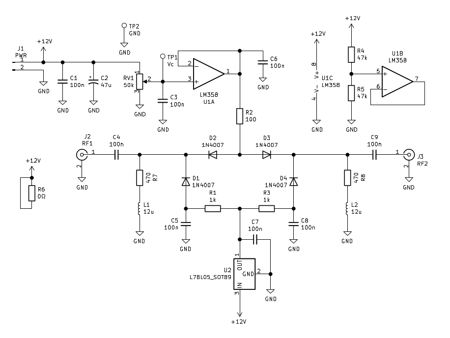
So I set to work adapting the above schematic for a little test board I could play with on the bench. I really wasn’t sure what to do for the resistor values, since I’m using a completely different diode. I figured they’ll probably need stiffer currents (not sure if that logic holds any water, hah!), so I reduced the resistor values a bit from what I saw in the IC-7300 schematic.
Icom uses some 100uH inductors to block RF currents from taking the easy path down the shunt resistors that facilitate bias current through the diodes. It makes sense, because they can then have the freedom to choose a resistor and current level for optimum performance. Unfortunately, I only had 12uH inductors lying around, so I had to go with those. I hoped that, worst case, it would just mean no 160m band for my attenuator.
If thought I’d just use a potentiometer for manual adjustment so I can test and play with it. Proving some sort of Murphy’s law of junk bins, I went looking for a decent linear potentiometer and only found logarithmic ones. I’m pretty sure if I was looking for an audio taper, I’d have only found linear ones. C’est la vie.
Construction
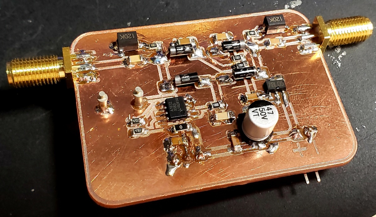
The board came off without a hitch. It’s been a long time since I milled a board, since I’ve been doing so many VHF and UHF projects. Glad to see the mill was in good shape despite probably 6 months of neglect. I decided not to tin plate it, as this is really just a quick proof of concept, and I was in a bit of a hurry:
There was one little short on one leg of the attenuator, which put initial current draw up at 49mA. Attenuation was very high, and not variable. Once I resolved the short, I found that the current draw was from 6mA to 18mA, depending on the value of the control voltage potentiometer. It’s not too bad, but perhaps a bit high if I was trying to be very battery-conscious.
Testing
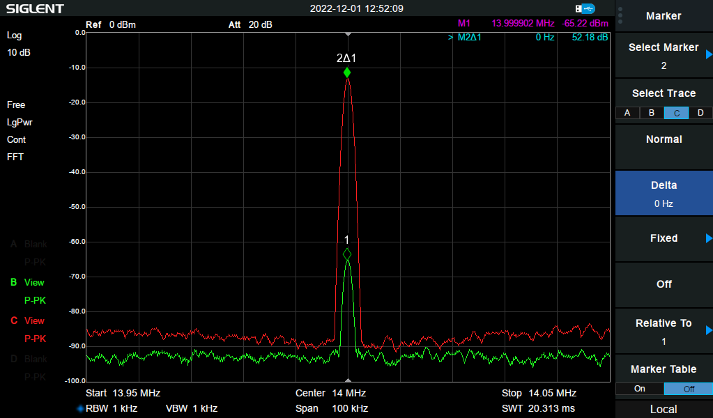
I did a few different tests. First, I connected my signal generator through it, observing the output on my oscilloscope. The result was really quite beautiful, with a smoothly variable attenuator (modulo the nonlinear curve of my potentiometer, grrr). I switched over to the spectrum analyzer to get some more precise measurements, and found that I had a smooth ~50dB of variable attenuation:
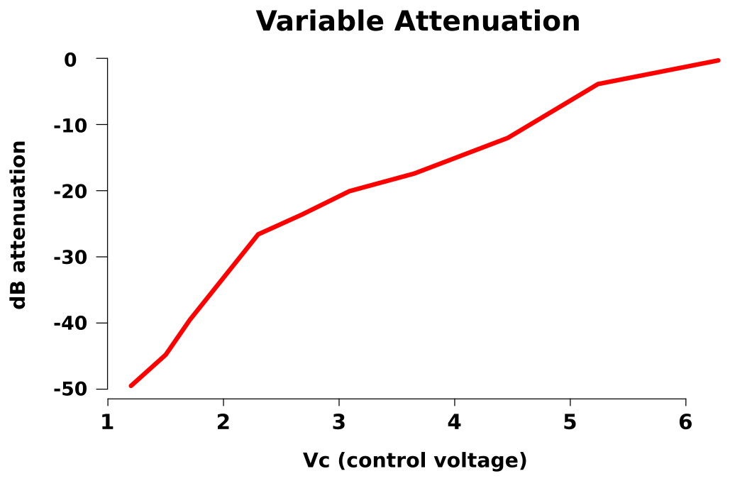
I took some measurements of the control voltage and resulting gain to make the following little graph. It’s a lot smoother than is suggested by the wobbly curve.
Finally, I set up the tracking generator and tested for wider-band performance. Here’s the behavior up to 100MHz (click for full resolution view):

On the 2m band, it ran from -3.8 dB to -30.33 dB and on 70cm it was -11.46 dB to -29.43 dB. I suppose it’s not really practical on those bands, but I could probably make some better component and layout choices. I don’t have any reference on what is the real, usable range of the 1N4007 as a PIN diode.
Conclusions
Having just ballparked a few resistor values, I was pretty happy with the result. I got -2.5 dB of insertion loss, which is pretty close to the figures in the HP application note. The behavior is very smooth, and much nicer than my previous attempts at variable amplifiers.
This approach should work great for adding some level control or AGC to my upcoming SDR project.