My First Transceiver
This post documents my first homebrew transceiver, from the ground up. By this point, I’ve built enough prototypes for different types of block elements that I might use, and it’s time to put it all together to make a real thing! I think I’d underestimated all of what goes into such a project, and I learned a whole lot from this adventure!
Starting Point
I have made some receivers and transmitters in the past, but always specific prototypes to test an idea or make sure something made sense. In all of my reading, I’ve seen consistently that writers encourage building a simple, direct conversion, CW transceiver as a first project. Though I’ve been playing with Tayloe detectors (e.g., this one) and sideband elimination, I decided to humble myself and start with something small. The block diagram for this project looks something like this:
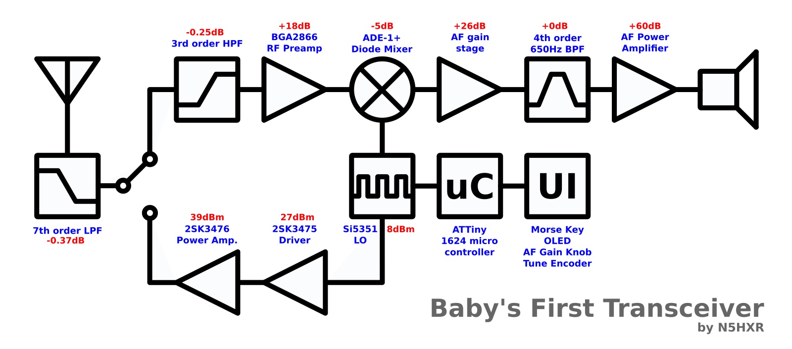
It’s perhaps worth discussing a few things there, as this is somewhat more complex than the typical first go. First, I have been reading a lot of EMRFD, and one thing the authors point out is that having a small RF preamplifier in front of the mixer is helpful for a few reasons. One, it alleviates some of the gain burden on the rest of the receiver, but most importantly they suggest it to block mixer leakage and tunable hum. These are negative effects of direct conversion receivers, and can be either annoying, or even compromise the usability of the device.
There are a bunch of different ideas about what should go there (as well as disagreement that it even should go there in the first place!). I thought I’d play a little bit, and toss in a little MMIC gain block. The BGA2866 has very high reverse isolation, and is already impedance matched to 50-ohms in and out. It did end up working for me, but I don’t believe it was ultimately the best choice.
Some of the people I talked to cautioned me that the intermodulation in the BGA2866 might be somewhat problematic. Its input IP3 is -4dBm, which they said might lead to unwanted distortion in the presence of loud signals nearby. I absolutely believe them on this, and agonized over it a little bit. But when I realized that a lot of people have built NE602-based DC receivers (IIP3 of -11dBm) and been happy with the results, I decided this is a complaint that is perhaps beyond my current level, and I’m not ready to care about that so much yet :-).
In retrospect, I might try something different here, but I went with it because if nothing else it’s unusual, and there’s no sense being too normal in life!
The next thing perhaps worth discussing is the input filtering. Of course most people use a low pass filter, to keep emissions within regulatory limits, at least. I thought I’d toss in an extra round of high pass filtering on the RX chain – DC receivers seem to be a bit famous for having front-end selectivity issues, and so I figured I’d hedge my bets on attenuating out-of-band signals like AM broadcast, etc.
Another zany thought I had was to use genuine RF power transistors. I could well have used something like a 2N3904 for a driver, and maybe an IRF510 for the final, but again… that’s normal. I have previously done some playing with these inexpensive UHF power transistors, and had positive results. So I thought maybe I could get some decent efficiency and power out of it (spoiler alert: turns out I get 8W, which is pretty awesome!).
I’m using the popular Si5351 for the LO, and embedding a little ATTiny1624 to control everything. By not using the ubiquitous Adafruit module (or a clone thereof), and embedding the uC directly on the board, I realized I could save a lot of space. I figured if I was going to make something simple, I may as well challenge myself to make it very small.
The Board
I whipped up a design in Kicad, and agonized over it for awhile. I really prefer milling boards because I can take risks – if something doesn’t work, worst case I can mill another one up :-). But if I have to order one, and it’ll take a week or more to arrive, I really hate making mistakes. I got it in pretty good shape, but still had to fix a few things anyway – it’s almost never perfect on the first try! The boards arrived, looking pretty good from JLCPCB:
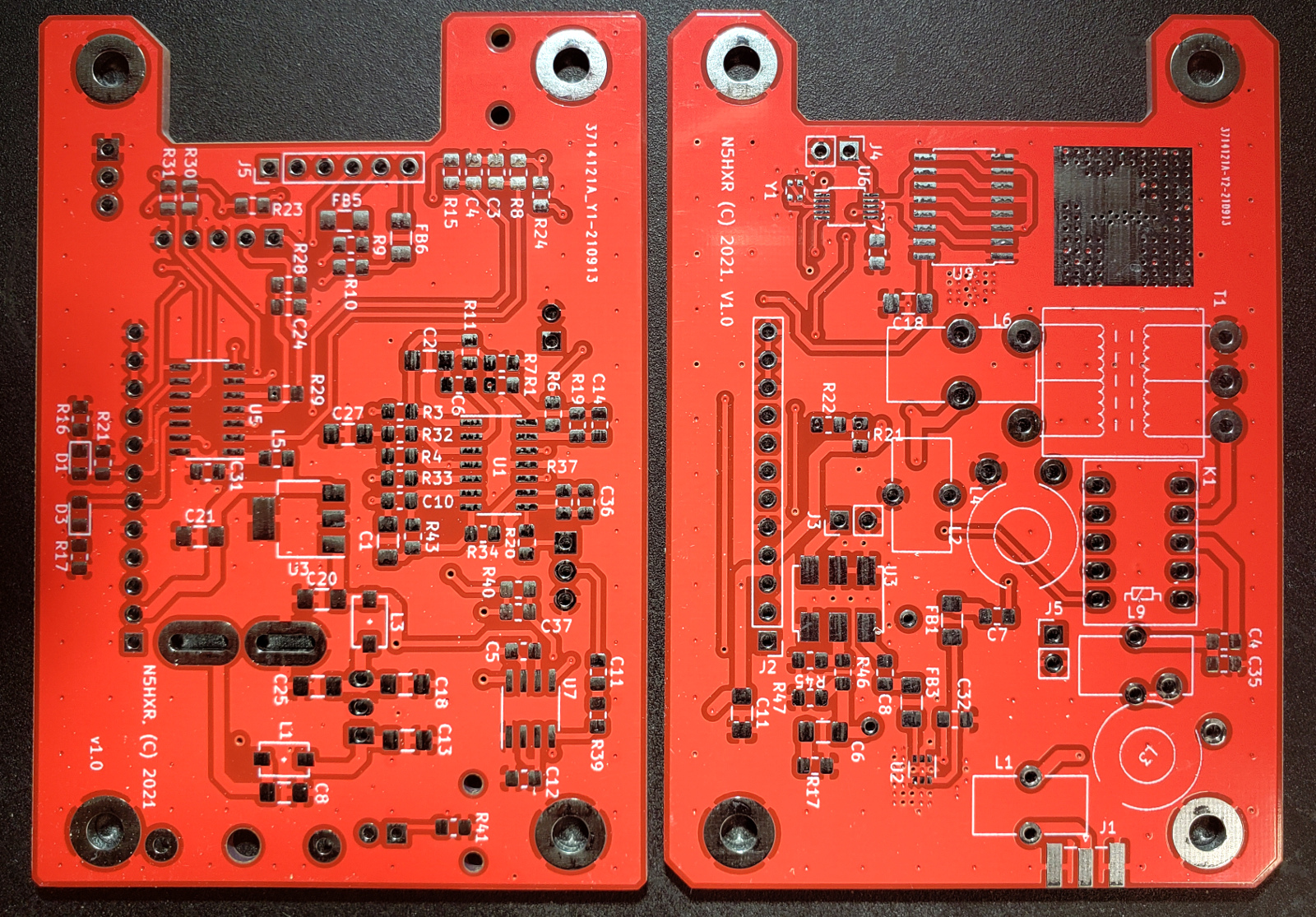
You might notice a few things I did on the board that are kind of fun. One is at the bottom left of the left-hand board in the photo: the power connector is a board-mounted Anderson PowerPole. It turns out the hardware for these is quite cheap, easily purchased from distributors like Mouser, and easy to use! Since I use these connectors on all my power supplies and batteries, it makes no sense to build in some other connector and require a pigtail.
The board on the left is the “AF Board”, whose schematic you can find here. The board on the right is the “RF Board”, with this schematic. I won’t rehash the details here, it’s not a very complicated design!
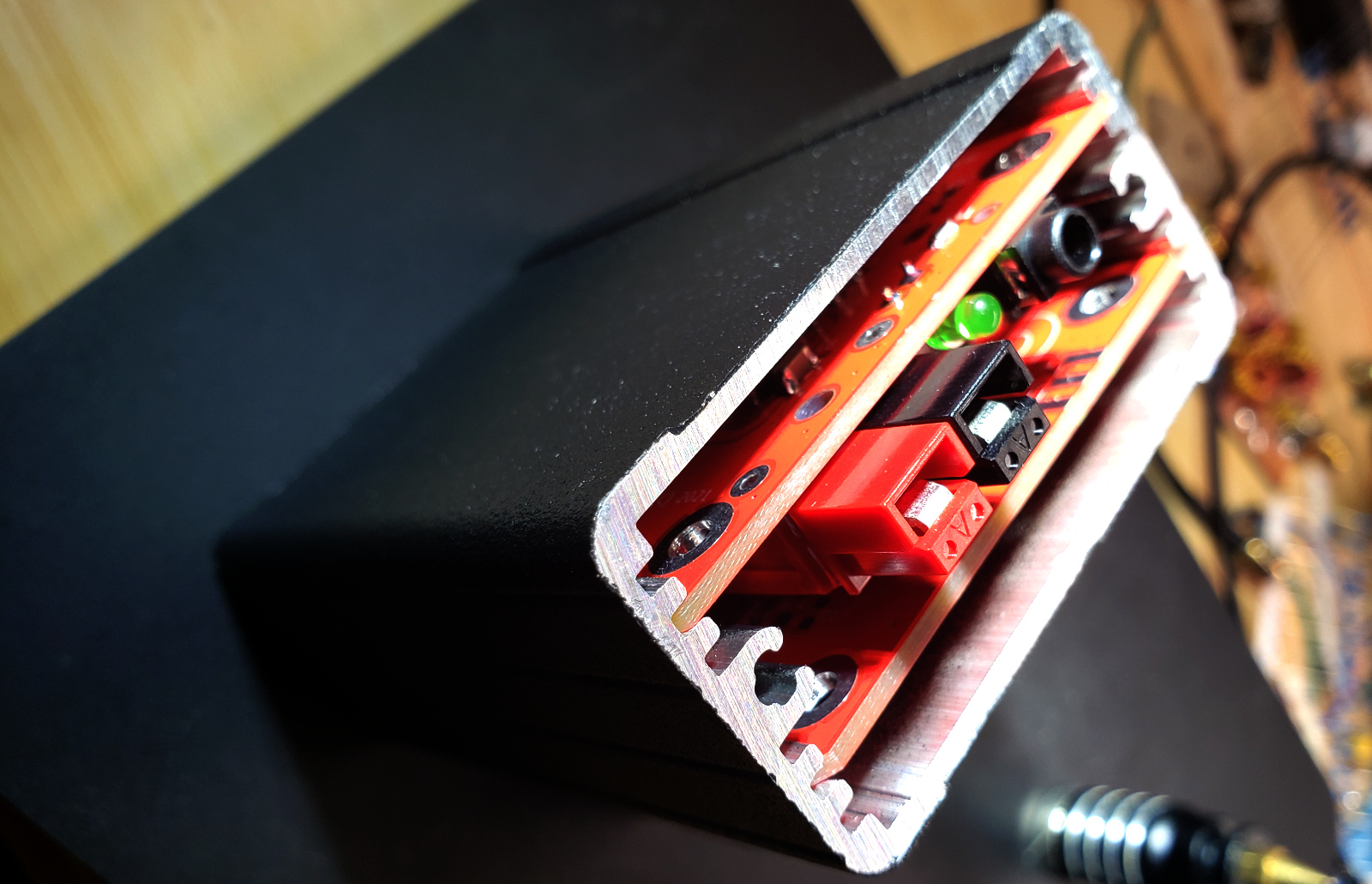
I designed it to fit into a beautiful little enclosure from Hammond (the 1457). This one is a single piece, with conductive gaskets for the end plates, which is supposed to make it really good for EMI / RFI. This rig isn’t really a high performance thing, but I though, “Why not?” The boards fit pretty well, though one was a bit tight and I had to do a little sanding to get it in!
Construction: AF Board
Assembling the boards went pretty well. I started with the power supply. I wanted to verify it was in good shape before building the rest (no sense frying parts unnecessarily!):
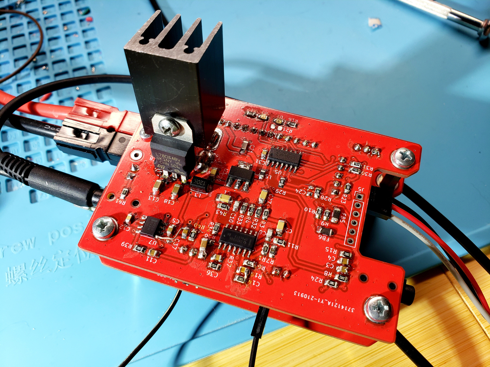
Everything was mostly fine… what is hard to see in the photo (because it’s on the underside of the board, hah!) is the R-78E switching regulator module. I’d used something very much like it in my build of the QCX, which had saved me a good 30mA of current draw. I thought it would be a good idea here, to keep wasted power down. But, unfortunately, I found that it was way too noisy, injecting a massive amount of switching noise right over the 40m band. I ultimately had to swap it out for an unsightly TO-220 LM7805 and a big heat sink (you’ll see that in other pictures of the final build).
That was probably the most frustrating aspect of the entire build – by being forced to change that regulator, the boards would no longer be able to fit in the intended enclosure. That means this transceiver will be a bench queen forever, and I’ll have to make a version 2 with a different power configuration in the future!
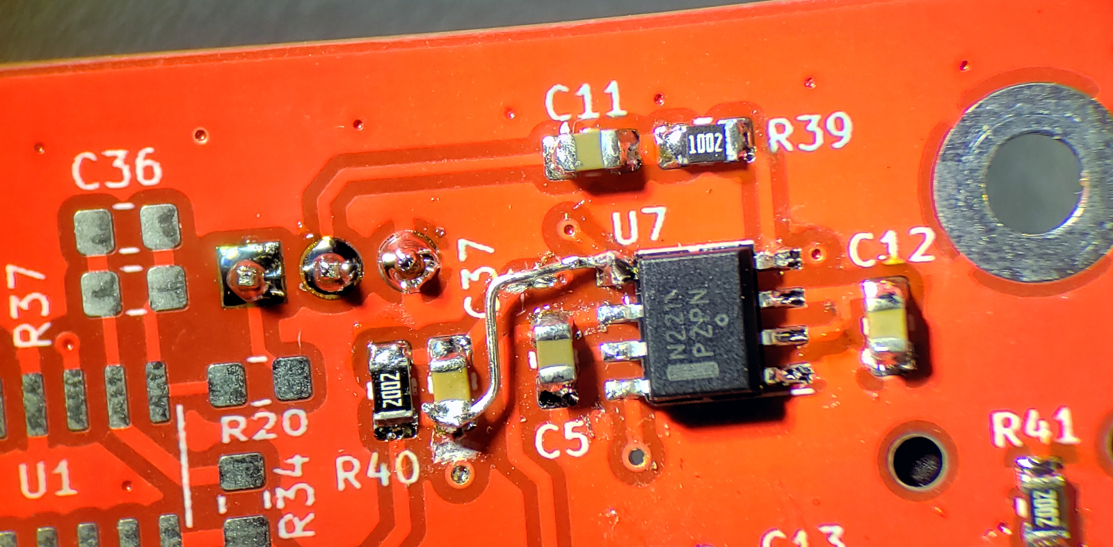
I proceeded on to the AF output chain, because it’s also easy to test with headphones. I added some leads so I could inject AF signals at the expected low levels, and test things out. (Note here you can see the unsatisfactory R-78E regulator…)
Unfortunately, I found a schematic capture mistake here, when I tried to use the AF amplifier. Instead of the common and old-school LM386, I opted for an NCS2211, which is a nifty modern part. Despite the agonizing I did on the schematic, I accidentally routed the feedback from the wrong differential output pin… a little bodge wire fixed it, and I have another little reminder for things to check in the future.
I had designed a modest fourth-order band pass filter for audio, hoping that would be pretty tight. In practice, it’s looser than I would have wanted, but the only way to improve that is to add another opamp to the board (trying to keep the parts list down!). Here’s a sweep of the AF bandpass filter on the scope:
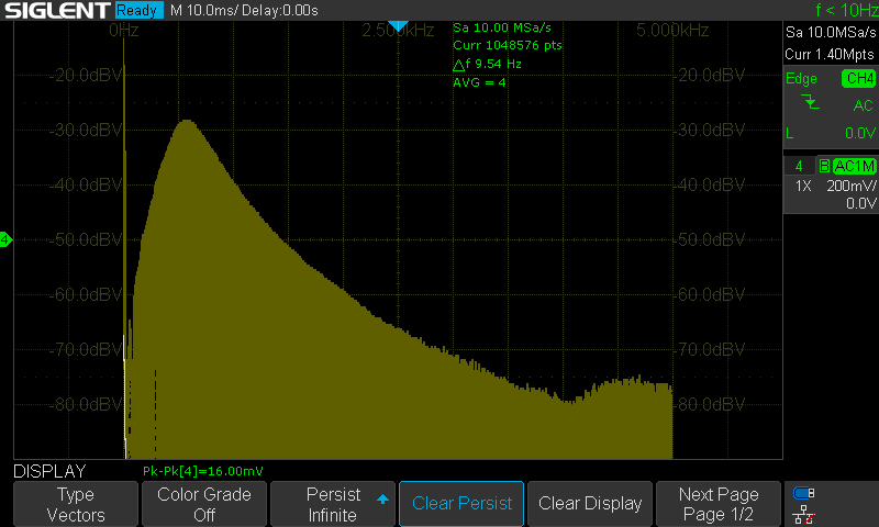
It’s worth pointing out here that I am really glad I bought a nice signal generator. I could generate this graph by configuring a slow sweep and using the infinite persistence feature on the oscilloscope in FFT mode. Quite a nice way to confirm things, since I don’t have anything like an audio frequency spectrum analyzer with tracking generator!
Construction: RF Board
The first thing I did on the RF board was to mount the RF power transistors. The 2SK3475 I used as the driver isn’t so bad, but the package for the 2SK3476 is a real pain to install. It’s a hefty package designed for a lot of power, and I had created a big matrix of vias to maximize thermal transfer to the other side of the board, where I would mount a heatsink. This means the pads soak a ton of heat, and it’s almost impossible to do this with an iron. It might not be so bad, but the source pins are so small, it’s really hard to get enough contact!
So, before doing anything else on the board, I thought I’d try hot air. It worked great – I tinned the source pad with some solder, fluxed the heck out of it, and placed the transistor. Enough heat, and it sucked itself right down, no problems at all. I’ll be using hot air for troublesome parts more often in the future!
![]()
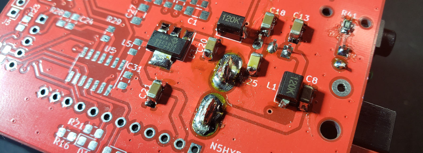
The rest of the RF board assembly went pretty uneventfully. There was one issue with reading the footprint from the crystal’s datasheet (for the Si5351’s reference). You can see it installed crooked to make up for that in the picture below.
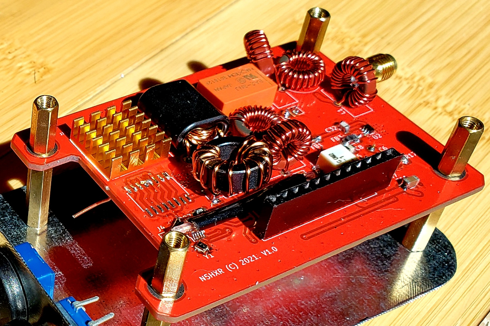
Another item worth noting is the unpopulated footprint between the Si5351 and the final’s heatsink. I had initially thought of using a logic buffer between the Si5351 and the 2SK3575. I thought maybe I’d get a faster transition to the “on” state, and get more efficiency. Boy was I wrong! The drain waveform looked like this monstrosity:
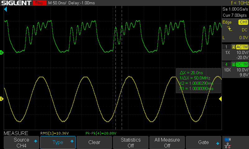
Apparently some of my reading about class-D and class-E amplifiers had led me to a poor understanding of some transistor physics. Some of the geniuses on the Facebook Ham Radio Homebrew group helped me understand that I was overdriving the driver, and pounding the final into the triode region (Vgs - Vth > Vds, wow!), something I’d never read about. Taking out the unnecessary buffer made things work much better.
There was also some oscillation and unnecessary heating, which was solved by adding a shunt capacitor, also recommended by the guys in the Facebook group. It’s so great to have access to good waveform whisperers!
Receive Testing
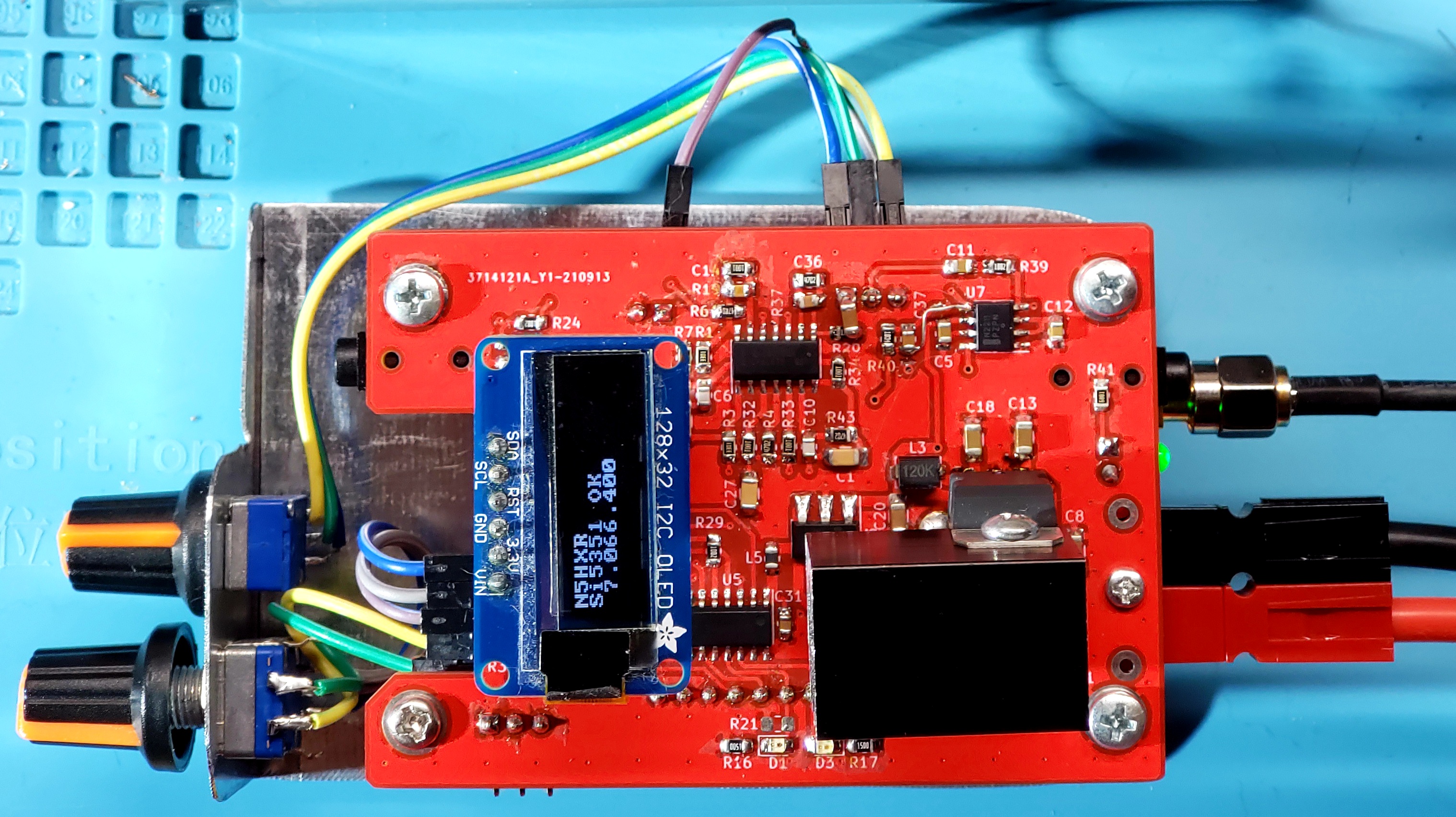
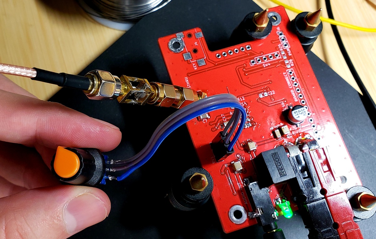
Once I had the RF board in working order, I could sandwich the two boards together, and really teste things. The first thing I found was the aforementioned switching noise at 40m. I went to some pretty extreme lengths trying to filter it, and ultimately was unable to improve things. There was just an incredible amount of noise in the receiver. When I finally gave up and removed the R-78E, replacing it with a linear regulator, suddenly things sounded wonderful! You can see the ugly, yet functional result here:
I did some testing, and found that MDS was quite low – I had no trouble hearing the noise floor on 40m, and can hear signals down in the S0 range quite well. Though it’s a DSB receiver, and thus has the obvious flaw of no sideband elimination, it is otherwise very pleasant to listen to. Just tuning around the band was fun. For a few days, I connected it to an external speaker, and just listened to 40m CW through the day while I was working. Quite pleasant.
Though it’s a CW rig, the receiver is more than sufficient to receive digital modes, like FT8. I ran it overnight, and picked up decodes all over the world:

Transmit Testing
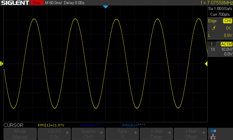
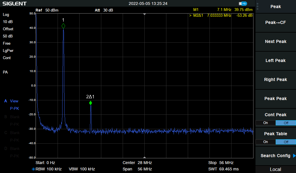
This is where things get interesting. I started measuring output power, and got things adjusted. Here’s an example of the output signal into a dummy load. With the supply voltage at a full 13.8V, it’s 9.6W of output power!
Testing on a spectrum analyzer shows that the 7th order filter is doing its job. Harmonics are at -53dBc, which means the transmitter can go on the air without reservation.
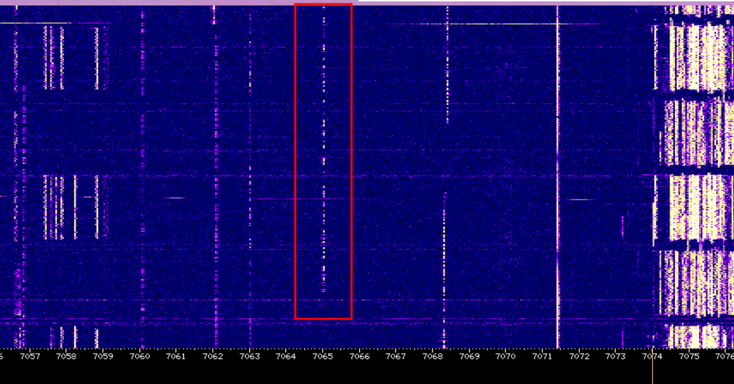
I thought I would do some testing with a WebSDR in Corinne, UT (it’s my favorite for testing). It’s about 1,700 miles away. I sent TEST N5HXR to see if I would get picked up by the Reverse Beacon Network too. I was quite happy to see that my signal was quite visible on the WebSDR!
There were some good results on RBN too, I was quite happy with this success. And then the scariest thing ever happened… somebody replied to me! I heard an N5HXR DE ... and my heart leapt through my chest.
I’d never had an actual CW contact before. I’d been working on my copy a bit, since I was building a CW transceiver and all. But this was a little too early, and I was pretty nervous. I replied. Something like, AGN PLS? DE N5HXR, and we went back and forth a few times to get callsigns exchanged. I told him it was my first CW contact ever, and I started to have some real trouble catching what he was sending back. I politely excused myself from the contact with a 73 DE N5HXR..., and had to sit back for a bit to let my heart rate go back down :-).
Conclusion
This project was quite successful. I would like to have been able to fit the boards in the enclosure, though, and not use that ugly LM7805. I will have to either make another revision of this transceiver to fit into it, or maybe use the enclosure for another project in the future.
I’ve now made several CW contacts using this rig, and it is quite functional. It’s kind of fun surfing the band with the DSB receiver, having to tune up and down to make sure which sideband a signal is in.
The biggest benefit of going through this was slogging through all the little details for TX/RX switching, fitting all the parts into one build, nothing modular like my previous projects. I think it was a very good idea to scale back my expectations to a simple DSB CW transceiver, so I could work through everything. My next transceiver projects will be easier, having worked out a bunch of these details that wouldn’t have really occurred to me otherwise!
Also, it’s a priceless trophy result that my first ever CW contact is also on my first ground-up transceiver build. These days, I don’t think that’s a very normative experience, and I’ll certainly treasure the moment for years to come!
If I were do the build again, I’d probably do a few things differently. The main change I’d make is to swap out the NCS2211 for an LM386 and the BGA2866 for something else in front of the mixer. Those are the only parts that need a 5V supply, and replacing them with 12V-capable parts would eliminate my need for a 5V linear regulator at all. If I go for round two, I’ll try changes along those lines, and see if I can fit it in the cool enclosure :-).